Communicating Furnace
INTE
GRATE
D FURNACE
CONTROL
A
U
X
I
L
I
A
R
Y
I
N
P
U
T
S
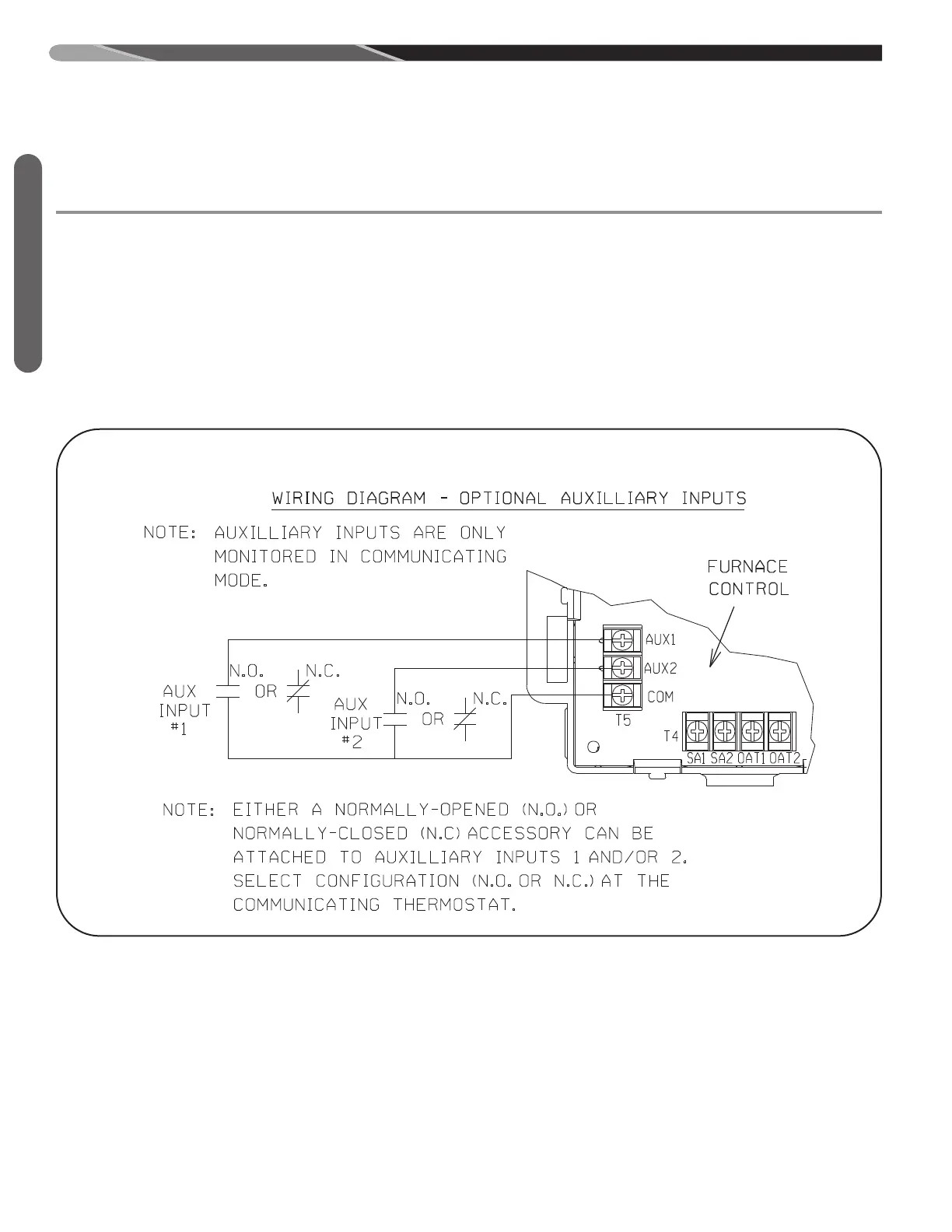
17. AUXILIARY INPUTS (COMMUNICATING SYSTEMS
ONLY) (T5) (SEE FIGURE 52)
Terminal T5 is porovided for field installation of up to
two auxiliary switches. The auxiliary inputs shall be
used to provide a means of using traditional drain pan
switches, smoke detectors, freeze switches, etc. The
inputs are to be labeled Aux 1 and Aux 2. The switch
inputs are for communicating systems only. One or
both inputs can be configured at the communicating
thermostat as either normally-opened or normally
closed contacts. System operation when the contacts
either open or close can be configured at the commu-
nicating thermostat.
A resistance of greater than 1k ohms to common shall
be detected as an open switch and a resistance of
less than 100 ohms shall be recognized as a closed
switch.
FIGURE 52
W
IRING OF AUXILIARY INPUTS (USE WITH COMMUNICATING SYSTEMS ONLY).
ST-A1194-63 (TOP)
98
 Loading...