17
INSTALLAZIONE
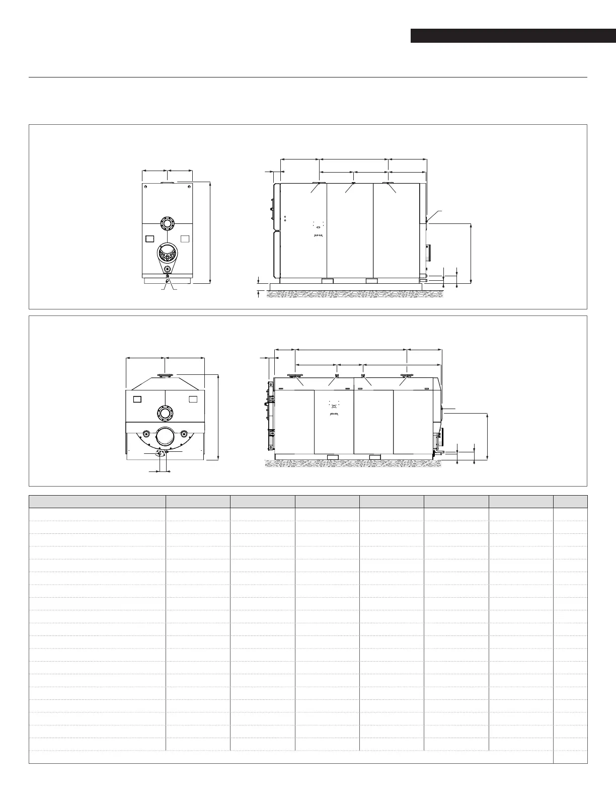
2.5 Collegamenti idraulici
Le dimensioni e il posizionamento degli attacchi idraulici della caldaia RTC è riportato nella tabella seguente.
Prima dell'installazione si consiglia di effettuare un lavaggio accurato di tutte le tubazioni dell'impianto per rimuovere gli eventuali
residui di lavorazione.
RTC 3000-RTC 4000-RTC 5000-RTC 6000
M M
L
56
N
4”
EDC
H
I
3
1 4 2
RTC 8000-RTC 10000
M M
L
6
5
N
EDC
3
44 21
H
I
DESCRIZIONE RTC 3000 RTC 4000 RTC 5000 RTC 6000 RTC 8000 RTC 10000
1 - Mandata impianto 4" #150 6" #150 6" #150 6" #150 8" #150 8" #150 Ø / DN
2 - Ritorno AT 3" #150 3" #150 4" #150 4" #150 6" #150 6" #150 Ø / DN
3 - Ritorno BT 4" #150 6" #150 6" #150 6" #150 8" #150 8" #150 Ø / DN
4 - Attacco valvola di sicurezza 2" NPT 2" NPT 2" NPT 2" NPT 2" NPT 2" NPT Ø / DN
5 - Scarico condensa 1 1/4" NPT 1 1/4" NPT 1 1/4" NPT 1 1/4" NPT 1 1/4" NPT 1 1/4" NPT Ø / DN
6 - Scarico caldaia 1 1/2" NPT 1 1/2" NPT 1 1/2" NPT 1 1/2" NPT 1 1/2" NPT 1 1/2" NPT Ø / DN
A 25.2 25.2 33.1 33.1 19.3 19.4 inch
B 50.4 59.8 59 66.9 100.4 114.2 inch
C 18.9 28.3 29.5 29.5 37.6 47. 2 inch
D 31.5 31.5 29.5 37.4 23.4 25.6 inch
E 31.3 31.2 32.5 32.5 39.4 41.3 inch
F 30.4 30.3 33.1 33.1 31.4 34.4 inch
G 46.9 48.7 51.5 54.7 41.7 45.3 inch
H 7.0 6.7 6.6 8.8 7.0 6.7 inch
I 2.5 2.4 2.6 3.3 5.5 4.5 inch
L 79.1 82.9 86.8 92.2 76.8 81.5 inch
M 19.7 20.7 21.7 23.0 35.4 37.4 inch
N 7.3 6.9 6.7 67 5.4 5.4 inch
O - - - - 5.6 5.4 inch
Flange as per ASME B16.5
 Loading...