Chapter 8 Protocol Decoding RIGOL
MSO1000Z/DS1000Z User’s Guide 8-3
D7-D0 8 0 D0 Bit0 to Bit7 are set to D0 to D7 respectively.
Bit0 to Bit7 are set to D8 to D15
respectively.
D15-D0 16 0 D0 Bit0 to Bit15 are set to D0 to D15
respectively.
D0-D7 8 0 D7 Bit0 to Bit7 are set to D7 to D0 respectively.
D8-D15 8 0 D15 Bit0 to Bit7 are set to D15 to D8
respectively.
D0-D15 16 0 D15 Bit0 to Bit15 are set to D15 to D0
respectively.
In additional, you can also modify the settings of Width, Bit X and CH
manually.
Note: This function is only applicable to MSO1000Z and DS1000Z Plus with the
MSO upgrade option.
4. Data Line Setting
Set the bus width
Press Width to set the data width of the parallel bus namely the number of
bits per frame. The default is 8 and the range is from 1 to 16.
Specify data channel for each bit.
Press Bit X to select the bit that needs to specify a channel. Press CH to
specify a channel source from CH1-CH4 or D0-D15.
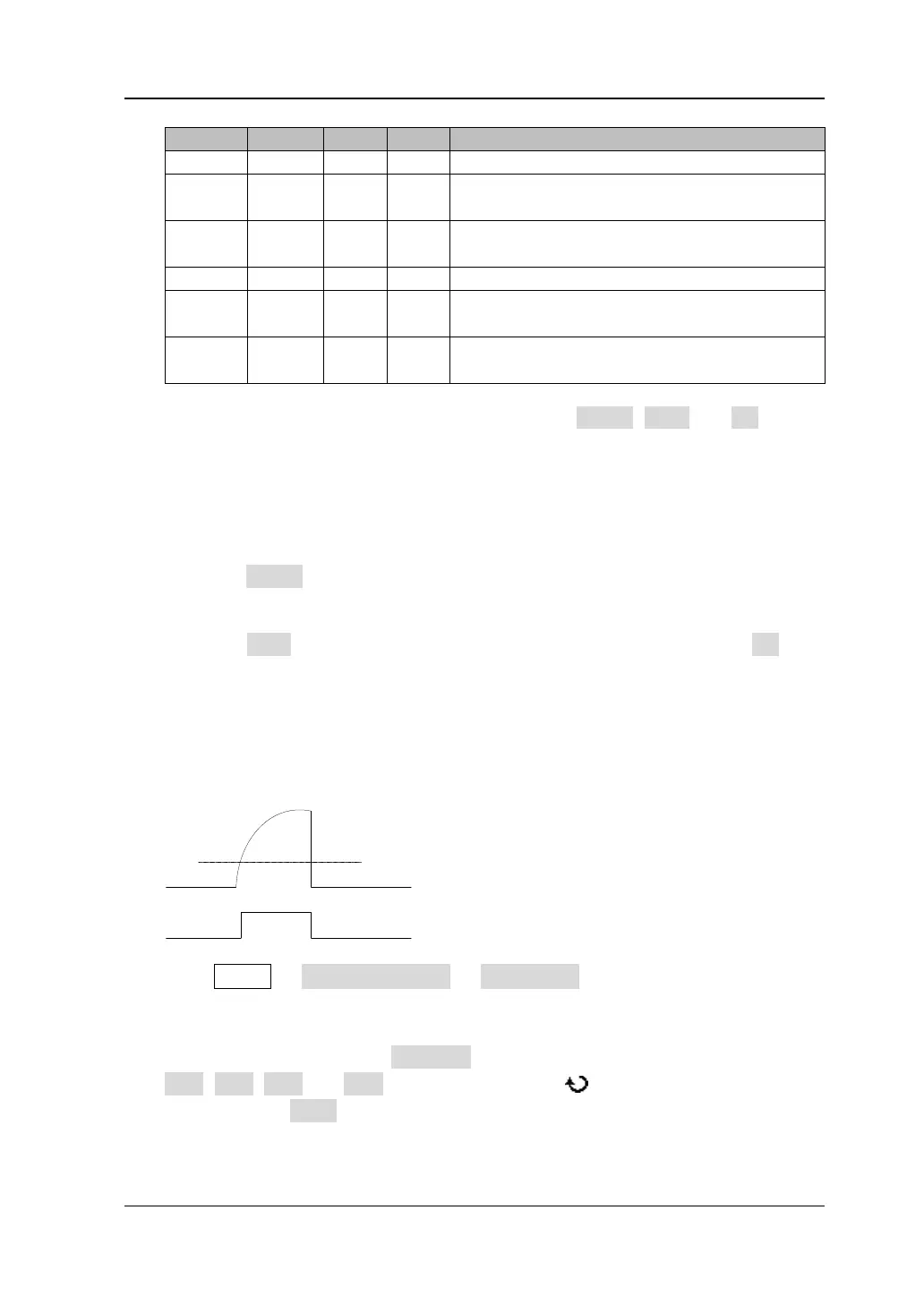
5. Analog Channel Threshold Setting
To judge logic "1" and logic "0" of the buses, you need to set a threshold for
each analog channel (CH1-CH4). When the signal amplitude is greater than the
preset value, it is considered as "1"; otherwise "0".
Press MATH Decode Options Auto Thre. to turn on or off the auto
threshold function. When auto threshold is turned on, the middle value of the
channel waveform is defined as the digital threshold level. When auto threshold
is turned off, you can press Thre.Set to enter the threshold setting menu. Press
CH1, CH2, CH3 and CH4 respectively and use to set the threshold of each
channel. Press 50% and set the current threshold to 50% of the current
waveform trace manually.
www.GlobalTestSupply.com
Find Quality Products Online at: sales@GlobalTestSupply.com
 Loading...