Linear ue installation guide 13541-A 01-20 | 13
Side extended ue assembly
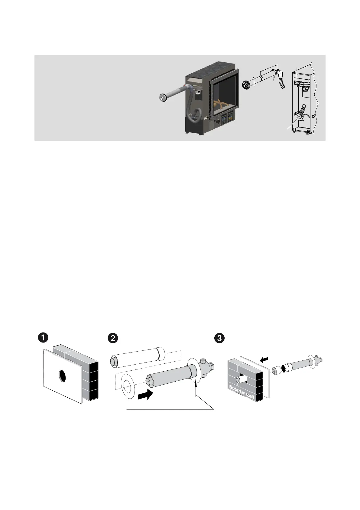
With the Linear installed into the support framing:
1. Create the wall penetration. The minimum diameter required is 80 mm to non-combustible
surfaces such as brick, and 100 mm to combustible surfaces such as plaster. Allow for a
continuous 2° fall from the Linear to the wall terminal.
2. Join the ESPIPE900 to the ASPDFK, t additional lengths of ue pipe as required. Components
do not require cutting to be joined. If cutting is required to achieve desired length ensure the
ASPDFK component is NOT LESS than 300 mm.
3. Slide the internal wall plate over the terminal end of the ASPDFK pipe until it is nested on the
raised ring of the ue transition.
4. Pass the ue pipe through the internal wall penetration.
5. Make the Linear exhaust and combustion air hose connections, refer p.9.
6. Slide the internal wall plate so it is ush with the wall.
7. Create the wall terminal, refer p.17.
The direct ue (ASPDFK) can be
extended if the wall thickness is greater
than 385 mm by using additional
lengths of pipe.
The ue must terminate 300 mm above
ground level.
ASPDFK
Air inlet pipe
outlet
M
i
n. 300
mm
Interior wall
Internal wall plate, outer face
Exterior wall
 Loading...