Linear ue installation guide 13541-A 01-20 | 17
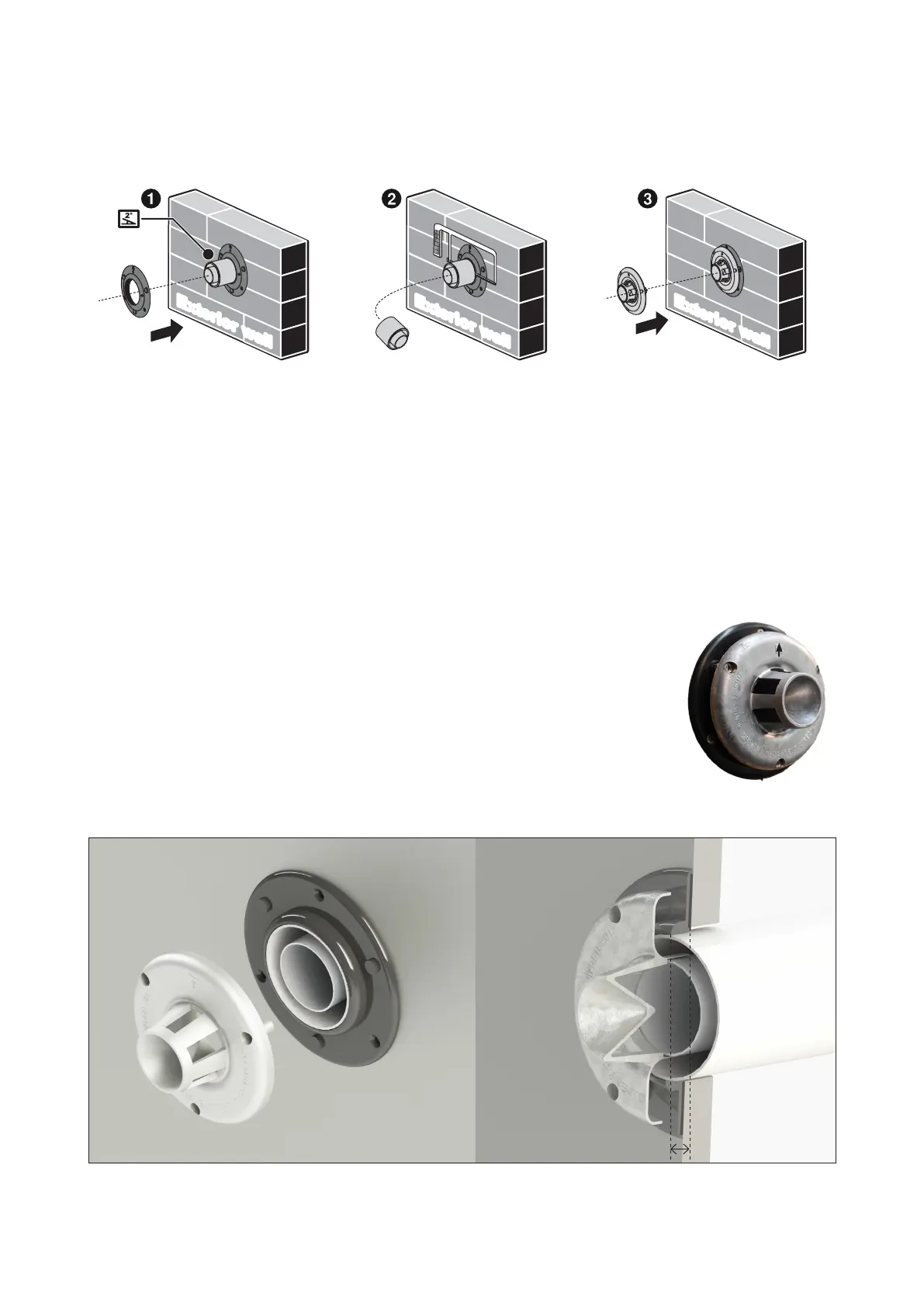
Steps to create a wall terminal
1. Fit the supplied external wall plate over the outer pipe of the ue protrusion (arrow points up)
Once the external wall plate is in the correct position secure it to the wall using the three 22 mm
screws into the wall plate holes. Secure the wall plate to the outer pipe using the two horizontal
holes and the two 7 mm screws provided.
2. Carefully cut through the outer and inner pipes ensuring the inner and outer are ush with
the external wall plate as shown below. Take care to avoid cutting the external wall plate, and
keep the cuts of the internal and external pipes as parallel as possible. Remove all burrs and
swarf from the cut ends.
3. Align the arrows of the metal ue terminal and wall plate to point in the
same direction (must always point up) and screw the terminal to the
external wall plate using the 22 mm screws into the holes provided.
E
x
te
ri
o
r
wa
l
l
E
x
te
ri
o
r
wa
l
l
E
x
t
e
ri
o
r
wa
l
l
2° fall to the outside—
arrow points up
Images showing how nal terminal should be installed
Approx. 14-16 mm
Please note: The ue protrusion from the wall is approx. 14-16 mm. It must not be more than this as it will create a gap
between the ue and the wall terminal, which will cause operational issues.
 Loading...