14 | Linear ue installation guide 13541-A 01-20
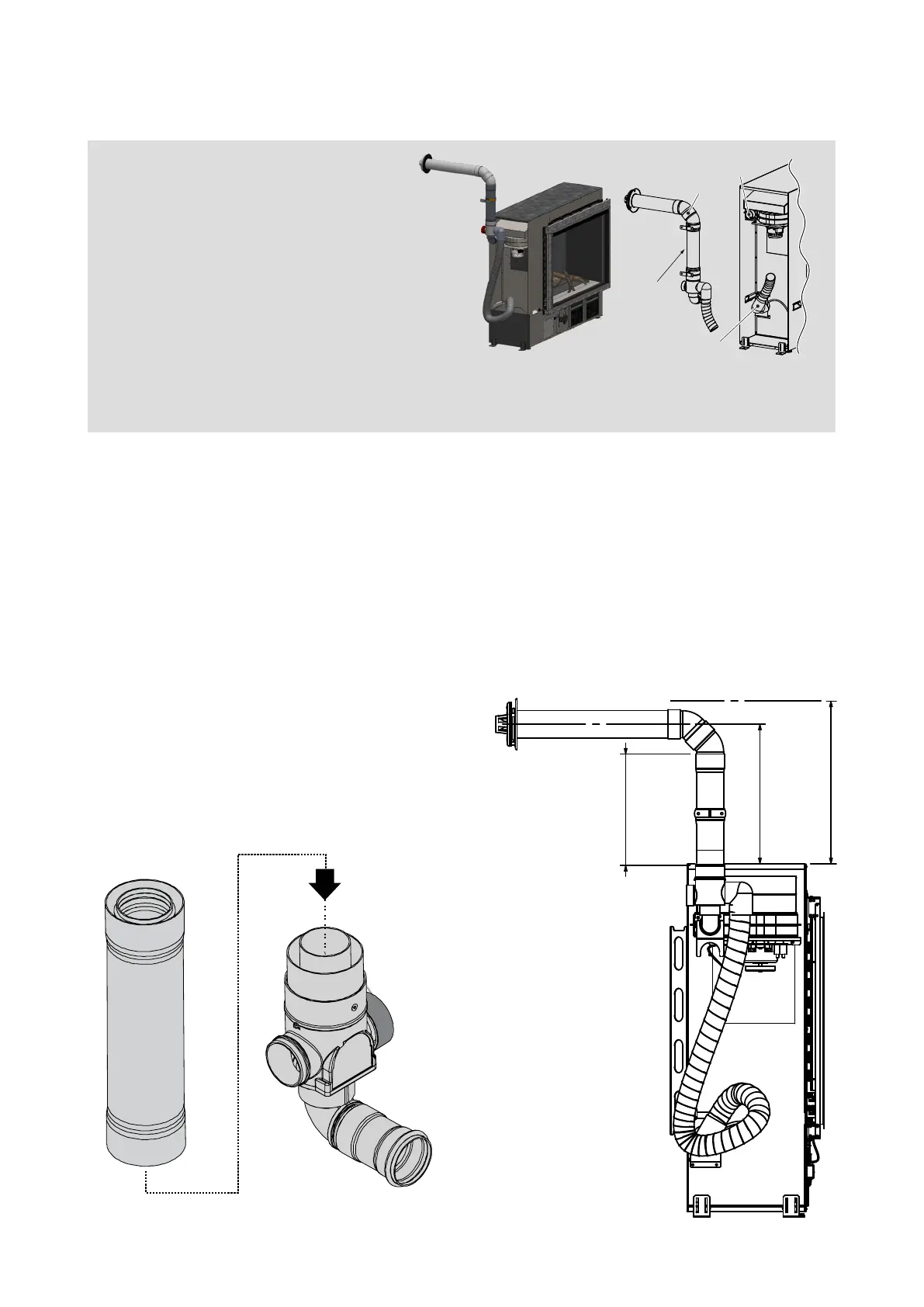
Up and back ue assembly
Air inlet pipe
Flue exhaust
outlet
45 ° bends
LSFKIT01
Up and back through wall ueing for
walls up to 385 mm thick. Flue can be
extended if the wall thickness is greater
than 385 mm by using additional lengths
of ue pipe.
A 2° fall is required towards the ue
termination. The ue must terminate
300 mm above ground level.
With the Linear installed into the support framing:
1. Assemble the ue components as pictured above. Ensure the ue transition section of the
LSFKIT01 is included. NEVER discard this section as this will cause an unsafe installation due
to a buildup of heat in the ue.
2. Create the wall penetration. The minimum diameter required is 80 mm to non-combustible
surfaces such as brick, and 100 mm to combustible surfaces such as plaster. Allow for a 2° fall
to the wall terminal.
3. Pass the ue pipe through the internal wall penetration.
4. Make the Linear exhaust and combustion air
hose connections, refer p.9.
5. Create the wall terminal, refer p.17.
~380 mm
300 mm min.
(top of adaptor
to first bend)
445 mm
(to clear flue)
LSFKIT01, ue transition
MUST BE connected
A minimum of 300 mm of straight ue before any bends. This is required due to the heat
produced from the initial section of ue, which could melt the outer plastic. The LSFKIT01 has
the 300 mm min. ue length built in.
 Loading...