Rockwell Automation Publication 440R-UM010C-EN-P - September 2016 23
Power, Ground, and Wire Chapter 3
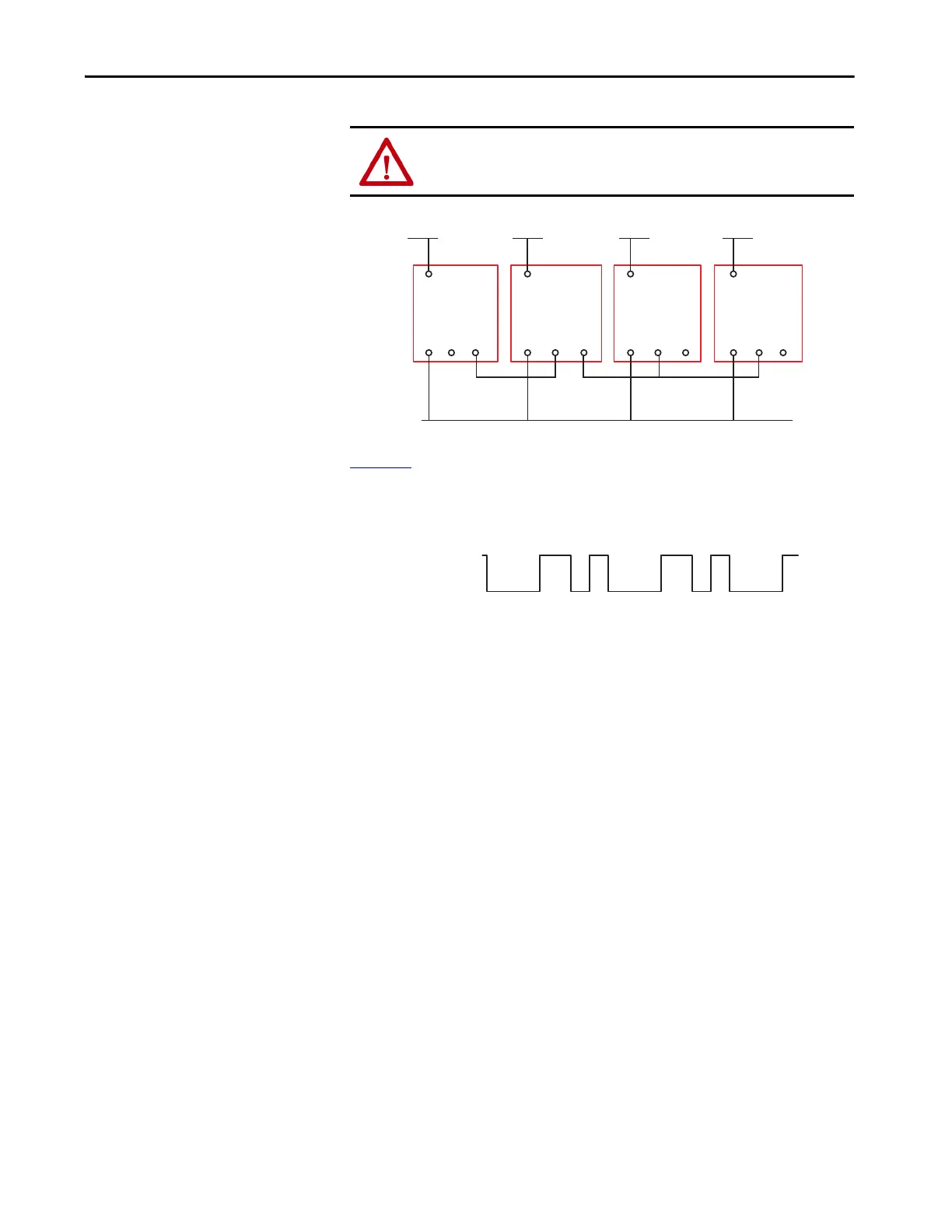
Figure 20 - Single Wire Safety Connections
Figure 21 shows the characteristics of SWS signal when it is active. It starts
with a 1 ms pulse, followed 600 µs later by a 600 µs pulse. This waveform is
repeated every 4 ms. When inactive, the SWS is 0V.
Figure 21 - SWS Waveform
ATTENTION: Do not use machine ground as the 24V common; connect the
commons of multiple power supplies using direct wire connections.
GLT
L12 L11
A1
A2
+24V DC +24V DC
24V DC Com
DI
L12 L11
A1
A2
EM
L12 L11
A1
A2
DIS
L12 L11
A1
A2
+24V DC +24V DC
Terminals
L11 and L12
24V
0V
10 1.6 2.2 4 ms