CIP Services and User-created Tags
54 Rockwell Automation Publication 1756-PM020F-EN-P - January 2019
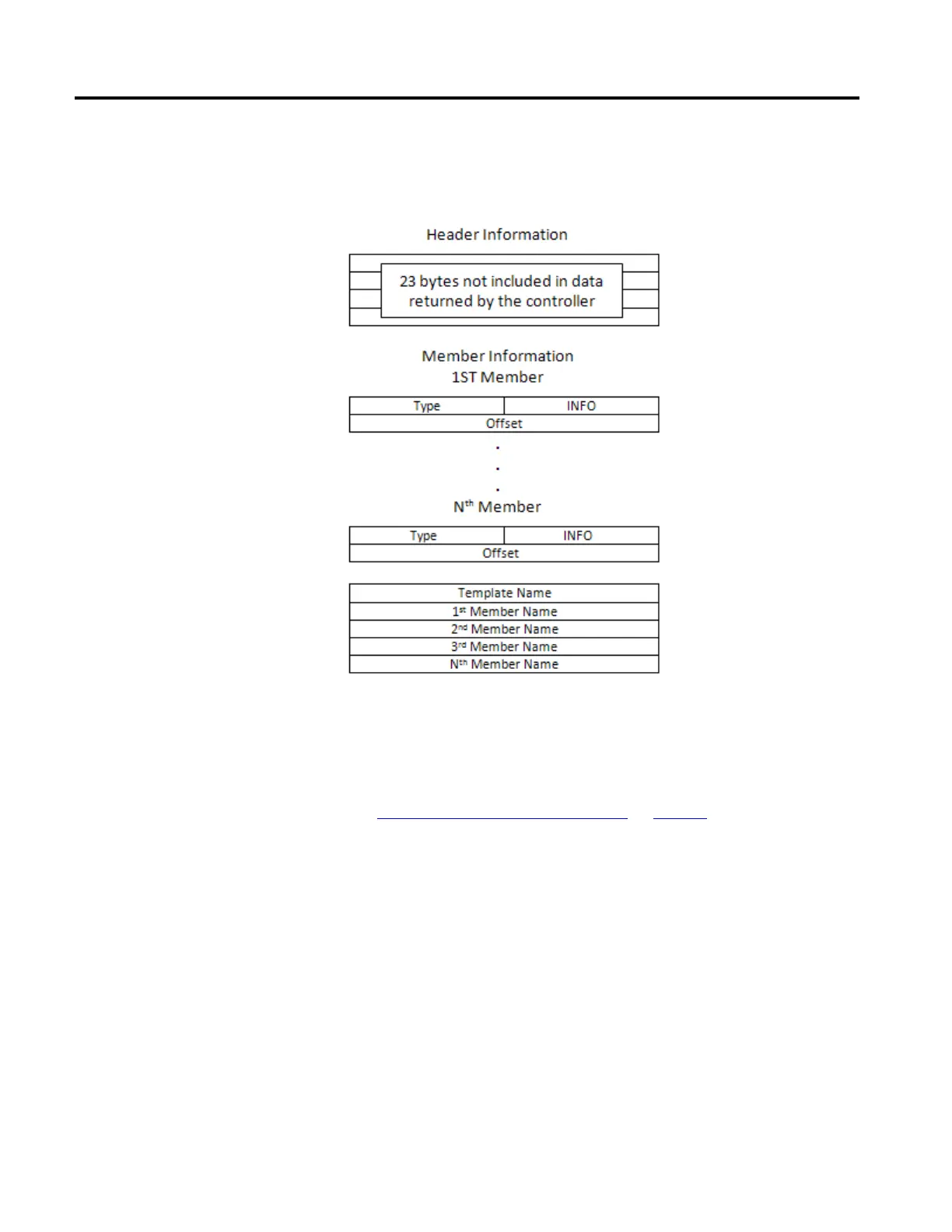
The structure data returned by the Template Read service has this format:
The response to the Template Read service is the Member Information in
Contents of the member information.
See also
Contents of the member information on page 54
The first 32-bit value contains:
• The lower 16-bits are the INFO value, which is one of these value:
• If the member is an atomic data type, the value is zero.
• If the member is an array data type, the value is the array size (max
65535).
• If the member is a Boolean data type, the value is the bit location
(0-31; 0-7 if mapped to a SINT).
• The upper 16-bits represent the data type.
• The second 32-bit value is the offset location of the member in the
UDT structure.
Contents of the member information

 Loading...


