14 Rockwell Automation Publication 7000-IN008D-EN-P - August 2019
Chapter 1 Receiving and Storing Procedures
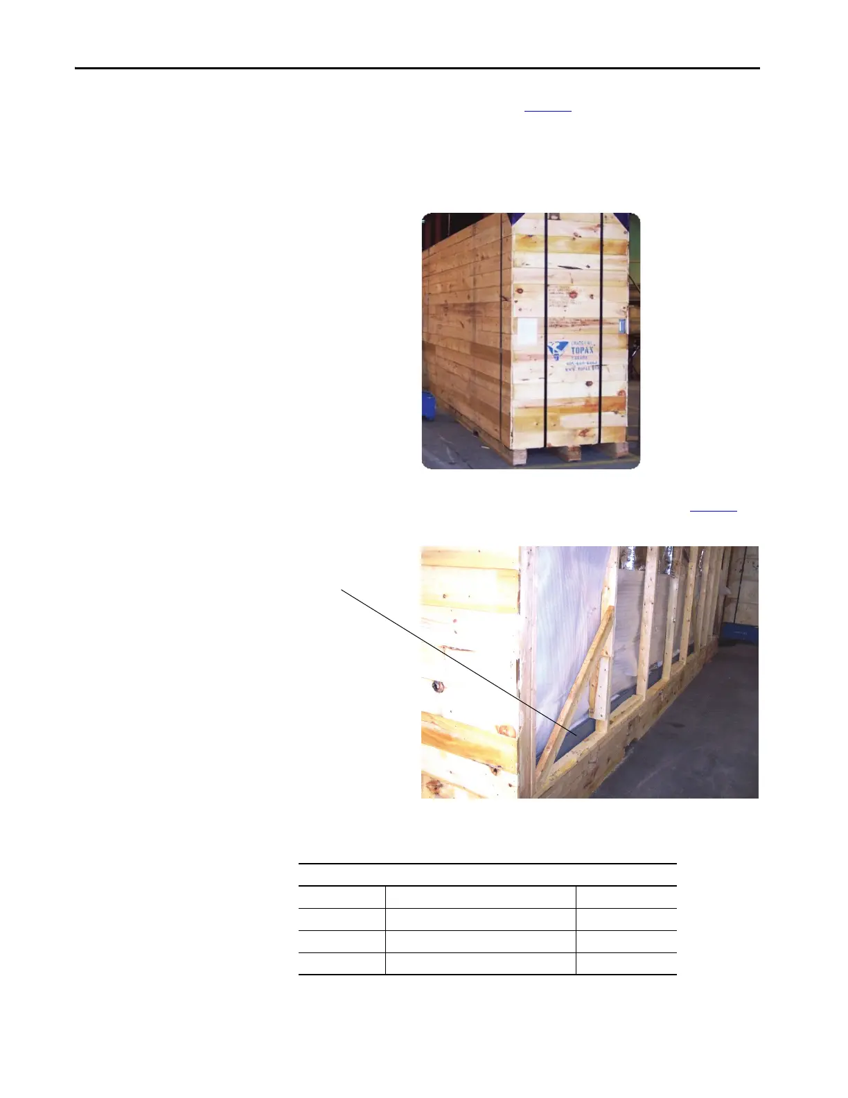
Export Crate
If the drive ships in an export crate (see Figure 6), the top lifting angles can be
inside the crate. Cables are outside of the crate for pulling the crate out of the
container. Not all export crates appears exactly as shown. See the instructions
supplied with the crate.
Figure 6 - Export Crating
Locate the pair of lifting angles (if included) inside the export crate (Figure 7).
Figure 7 - Location of lifting angles in export crate
Handle the lifting angles with care. Most versions are very heavy (refer to the
following table for dimensions and weights).
Install the lifting angles prior to moving the drive.
Pair of Lifting Angles
(2) and Hardware
Examples of Various Dimensions and Weights of Lifting Angles
Length each Dimensions Weight each
3 m (9.8 ft) 63 x 50 x 10 mm (2.5 x 2 x 0.375 in.) 13 kg (30 lb)
7 m (23 ft) 125 x 75 x 10 mm (5 x 3 x 0.375 in.) 105 kg (230 lb)
7 m (23 ft) 175 x 100 x 10 mm (7 x 4 x 0.375 in.) 140 kg (308 lb)

 Loading...


