16 Rockwell Automation Publication 7000-IN008D-EN-P - August 2019
Chapter 1 Receiving and Storing Procedures
The lifting angles hold the cabinets together to prevent separation and damage
while riggers move the drive to the final installation area. Remove the lifting
angles before attaching cooling fans and fan enclosures.
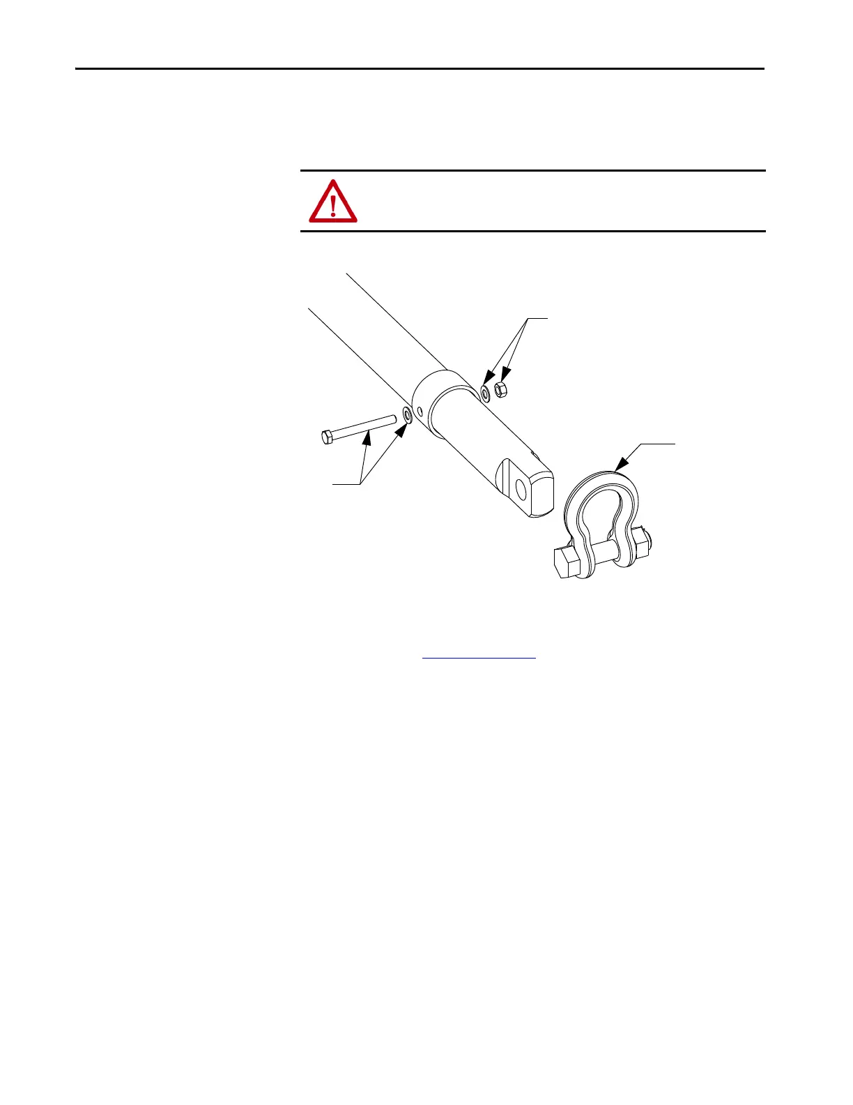
Figure 10 - Shackle Attachment, Bottom Lifting Bar
For drives with bottom lifting provision, attach the locking collars and shackles
(included) to the bottom lifting bar. Rotate the bar if necessary to suit the
available rigging. See Figure 5 on page 13
.
Accessories
Accessory items can ship with the drive. During the post-delivery inspection,
locate all accessories or loose items listed on the shipping documentation before
moving the drive to an installation or storage area.
Magnetic devices such as DC link, common mode choke, or line reactors can ship
separately from the drive because of weight. Install these items once you install
the drive in its permanent location.
ATTENTION: Failure to install the pair of lifting angles prior to moving the drive
can result in personal injury and/or equipment damage.
M12 washer, nut
M12 bolt, washer
Shackle

 Loading...


