3050-8010
Einbau- und Betriebsanleitung
Installation and Operating instructions
Instructions de montage et de service
Regeltechnik Kornwestheim
GmbH
Max-Planck Straße 3
D-70806 Kornwestheim
Telefon +49 7154 / 13 14 - 0
Telefax +49 7154 / 13 14 - 31
Internet www.rtk.de
E-Mail info@rtk.de
- 31 -
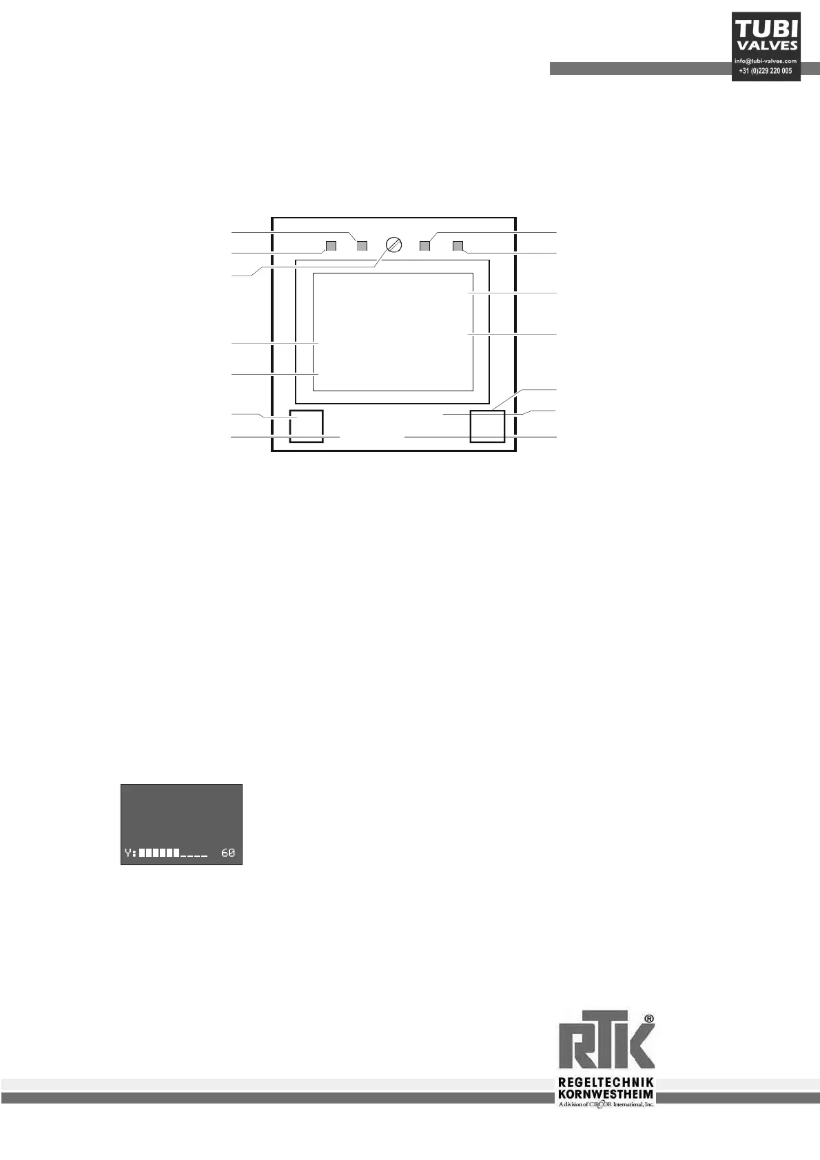
5 Operation
5.1 Frontal view
Locking screw: it secures the instrument insert in the housing.
LED’s: display the state of the controller outputs Y1, Y2 and alarms LIM1, LIM2
Display 1: displays the current value at the operating and parameter level,
but the configuration code at the configuration level.
Display 2: displays the pre-set value at the operating level during automatic operation and
the manipulated variable during manual operation. the values can be adjusted directly
with the cursor arrows.
Text 1: displays the short dialogue or the unit of display 2.
Text 2: only RE3053 displays the bar graph of the manipulated variable.
PC-interface: PC connection for configuring, creating parameters and operating
with the engineering tool
5.2 Status displays
60
FAIL
ÀC
160
8.8.8.8
8.8.8.8
ÀC
Y:ûû ûûûî 55%
LED 2 eg cooling
LED 1 eg heating
Looking srew
Text1 eg physical unit
Text 2 eg bar graph / dialog
PC interface
Manual / automatic key
LED 3 eg alarm1
LED 4 eg alarm2
Display 1 eg process value
Display 2 eg set point
Selector- key
Increment- key
Decrement- key
H D
I
P
This message signals a sensor error.
Possible cause: Break or false polarity at thermocouple
Break or false polarity
Break or short circut at Pt100 and remote sensor
Break at 4..20mA and 2...10V standardized signal
Y:ûûûûûû____ 60
 Loading...