3050-8010
Einbau- und Betriebsanleitung
Installation and Operating instructions
Instructions de montage et de service
Regeltechnik Kornwestheim
GmbH
Max-Planck Straße 3
D-70806 Kornwestheim
Telefon +49 7154 / 13 14 - 0
Telefax +49 7154 / 13 14 - 31
Internet www.rtk.de
E-Mail info@rtk.de
- 42 -
9 Alarm configuration
Up to four alarms can be configured They are allocated to the various outlets. In
principle each of the outlets OUT1, OUT2, OUT4, OUT5 may be used to signal limit values or alarm conditions
(if not already used for other signals).
Each of the four limits LIM1 ... LIM4 has 2 switch points LimH (Max) and LimL (Min), which may be
switched off separately (Parameter = “ ---- ”). The switch difference Lxsd of each switch point is
adjustable.
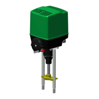
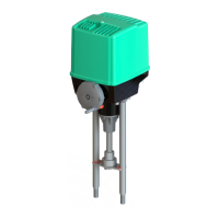
Functioning of absolute limit contacts LimH / LimL
❶Closed-circuit current, ❷Operating current . LimL
LimLLimL
LimL and LimH
LimHLimH
LimH represent the values at which the alarm is activated.
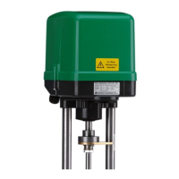
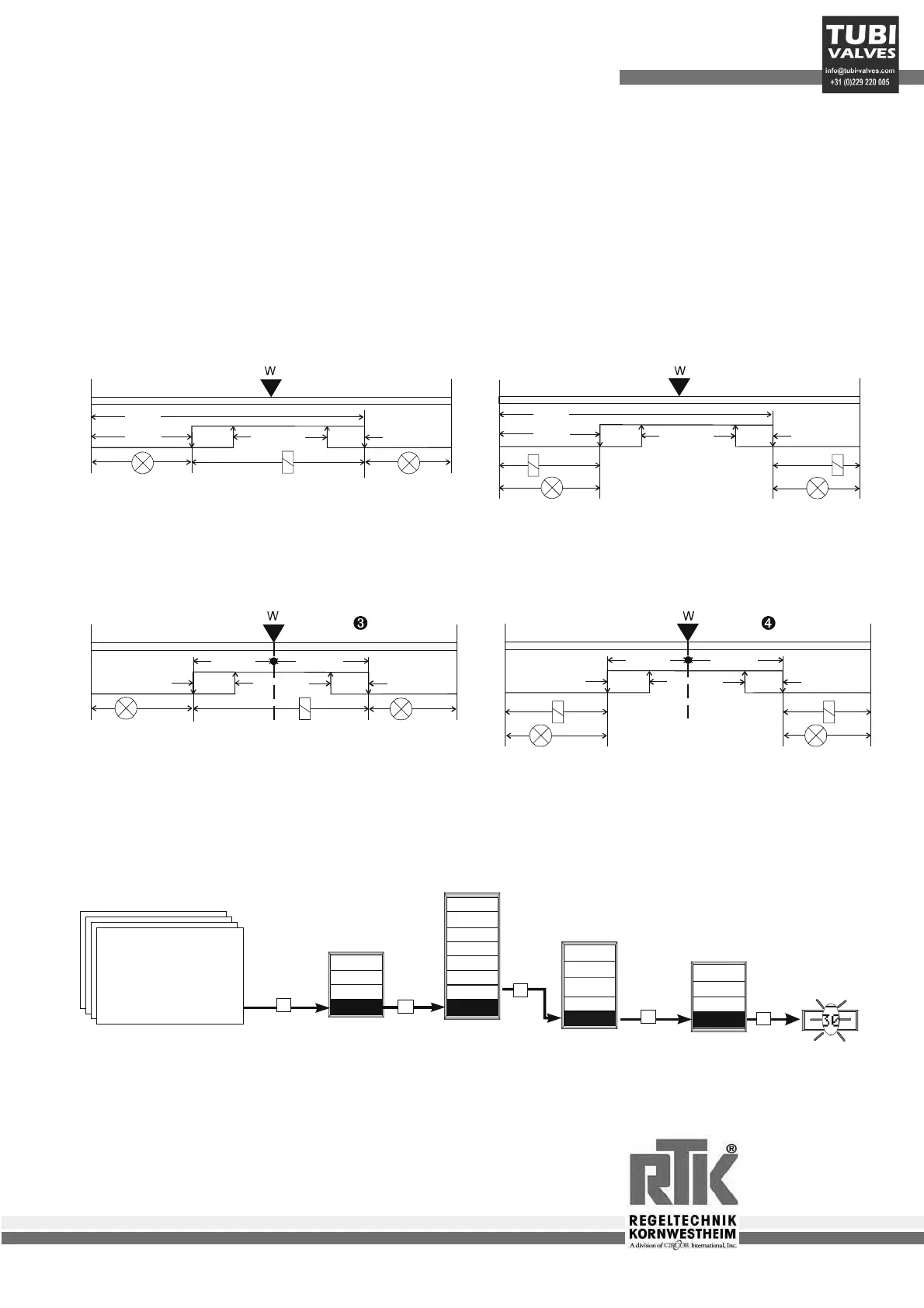
Functioning of relative limit contacts LimH / LimL
❸ Closed-circuit current, ❹Operating current . Lim
LimLim
LimL and LimH
LimHLimH
LimH represent the
deviations (x-w), at which the alarm is activated.
a
Limit values lower than the set value must be entered with a minus sign!!!
-999
-999
LimL
LED LED
LED
LED
Lxsd
Lxsd
Lxsd
Lxsd
LimH
x0 x0
x100
100
LimL
LimH
9999
999
2
1
-999
-999
LimL
LimL
LED
LED
LED
LED
Lxsd
Lxsd
Lxsd
Lxsd
LimH
LimH
9999
x0 x0
x100
>3s
End
Hold
OStar
Para
xs
End
gn
Aux
npu
on
r
Tune
m
e
p
I
D
I
D
+
+
+
+
+
270
Man.
xw____áûô___ 12%
10.5
LIM3
LIM2
LIM1
P
P
P
P
P
m
m
n
0.0
LIM4
n
 Loading...