EasyManua.ls Logo

Ryobi BDS4600 User Manual

Ryobi BDS4600
21 pages
To Next Page IconTo Next Page
To Previous Page IconTo Previous Page
Page #5 background imageLoading...
Page #5 background image
I
MOUNTING
BEET
AND
DISC
SANDER
TO
WORKBENCH
lf
belt
and
disc
sander
is
to
be
used
in
a
perman'ent
location,
it
should
n"
iuri"nio:securely
to
a
1rm
supporting
tutfr""
such
as
a
workbench'
lf
mounting
to
a
workbench'
holes
should
be
drilled
i;;;;;ii'
;ripporting"'suriace'ot
the
workbench
usins
dimensions
illustrated'
1.
The
unit
shoutd
be
bolted
securely..uslno
.s91ew1a1!
hex
nuts
(not incf-uieO)'
-screw.tenlth
should
be
38mm
pf
ut
tf,"
thickness
of
the
benchtop'
2.
Looate
and
mark
the
holes
where
belt
and
disc
sander
is
to
be
mounted'
3.
Drilltwo
diameter
holes
through
workbench'
4.
Place
belt
and
disc
sander
on
workbench
aligning
holes
-
;;;;*it
r'ot"t
drilled
in
workbench'
5.
lnsert
two
screws
and
tighten
hex
nuts'
Analternatemethodofmountingistofastenbeltanddisc
sander
to
a
mountinq
bliro
ihe
board
should
be
of
sufficient
size
to
uuo'iiipping
of
sander-while
in
use'
Any
;;;;;;o;
ol
prv*o'ii
o"r
chipboard
with
a
lemm
minimum
thicKness
't
"'"***tnded
(Thinner
chipboard
can
break.)
CAUTION:
To
avoid
iniury
from
tool
movement'
use
8mm
or
larger
screws
and
nuts'
1.
Follow
rnstructions
f or
mounting
to
wgrf
U-91q!t
'
s,iosiiiuting
a
ooiro
457mm
x 6.1Omm
minimum
stze
and
using
ttat
neiicrlws'
lockwashers'
and
hex
nuts
(not
rncludeOl.
ScLw
fength
should
be
38mm
plus
the
ir'i.xn"..
of
the
mounting
board'
Note:
For
proper
stability,
holes
must
be
countersunk
so
screw
heads;;;'ii';;
;ith
the
bottom
surrace
or
suPPorting
board'
CAUTION:
To
avoid
iniury
from
tool
movement'
;tn*i
:m
ll'kY*;::'P:'
I'1,,,m",'.xl$i!
ii
insurethatnomo,ementduringusecanresult.lfany
iifii;d';;
*rixi"g
it
noted'
l-""-Y,t-"
workbench
or
supporting
","""o"
before
operating
belt
and
disc
sander.
I
CLAMPING
BELT
AND
DISC
SANDER
TO
WORKBENCH
61cfr.-r
l-
I
outline
of
Sander
EI
s
{r
T-=
-:'
a-l l:-
::'
-=
--.-'
y;Orrb€.C.
_S
-
I
:,',
-
a'
-'
-"=
rn no . )a..')
-'
:1-'
a':
-'
-
\vr
vv
^
- -_-.:
l
'!-t
,,
lo 3
-
A
!=J
'J'
ts_.'
'"
:
;-::
--
::::
:'
'-
'
Fig
1
gaao
6
ISSEMBLY
Question and Answer IconNeed help?

Do you have a question about the Ryobi BDS4600 and is the answer not in the manual?

Ryobi BDS4600 Specifications

General IconGeneral
BrandRyobi
ModelBDS4600
CategorySander
LanguageEnglish

Summary

Safety Instructions

Before Using the Sander

Pre-operation checks, learning controls, and understanding safety rules.

Installing or Moving the Sander

Safe placement, environment, and handling to prevent injury.

Before Each Use

Essential pre-use inspection and checks for damaged parts.

General Safety Precautions

Broad safety advice on environment, tools, clothing, and operations.

Specifications

Product Details

Lists model number, power, belt/disc sizes, and table dimensions.

Electrical Requirements

Connecting to Power Supply

Details on grounding, outlet type, and electrical safety warnings.

Unpacking and Contents

Tools Needed

Lists the necessary tools for assembly and setup.

Checking Contents

Verifying all parts are present before assembly.

Assembly

Mounting to Workbench

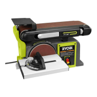
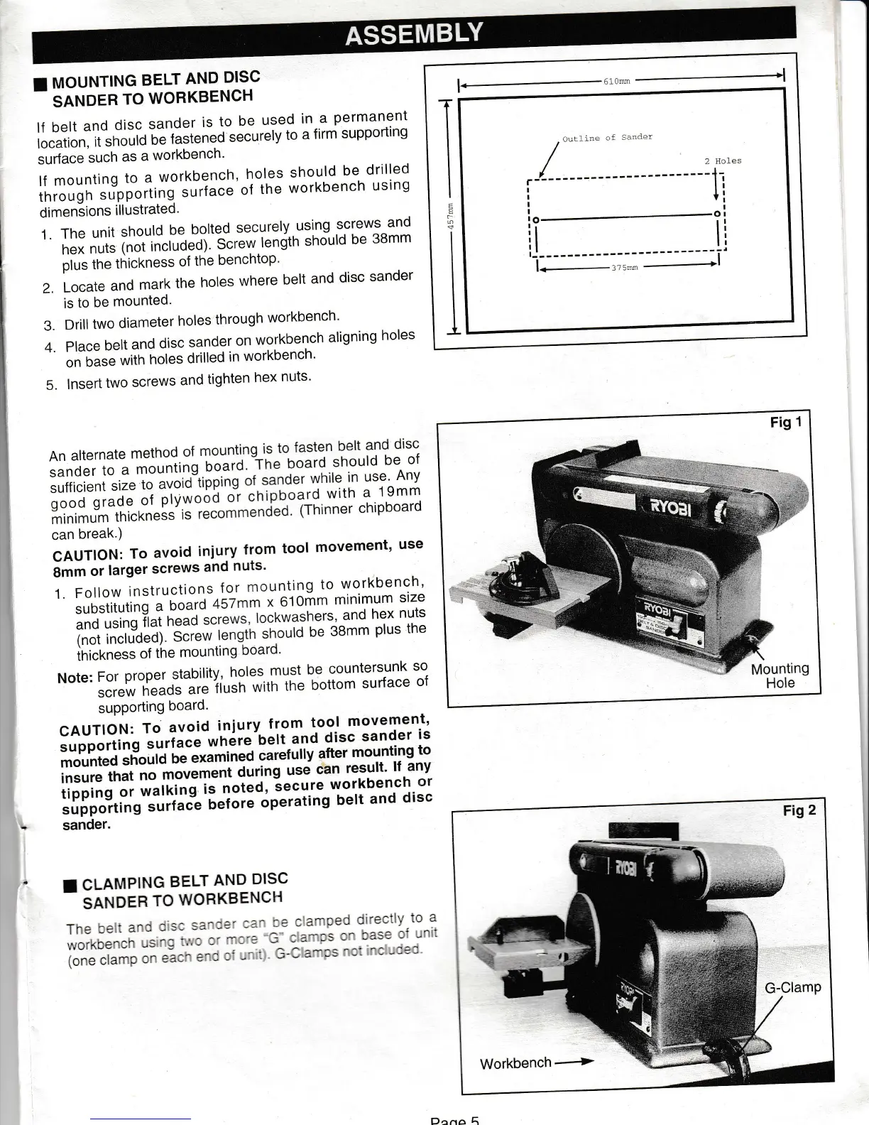
Instructions for securely fastening the sander to a workbench.

Clamping to Workbench

Alternative method for securing the sander using clamps.

Installation Procedures

Sanding Disc and Guard Installation

Steps to install the sanding disc and its protective guard.

Work Support Stop Installation

How to fit the work support stop for workpiece stability.

Table Assembly Installation

Details on fitting the table assembly to the sander.

Setup and Adjustments

Auxiliary Mounting for Vertical Sanding

How to set up the sander for vertical sanding operations.

Squaring Table Assembly

Ensuring the worktable is at a 90-degree angle to the disc.

Belt Tensioning and Tracking

Adjusting belt tension and ensuring proper belt alignment.

Component Identification

Main Components Overview

Identifies and describes the main parts of the belt and disc sander.

Switch Operation

On-Off Switch Functionality

Explains how to use the switch and its safety locking feature.

Basic Operation

Bevel Sanding

Instructions for tilting the worktable for bevel sanding.

Adjusting Horizontal to Vertical Position

How to change the belt assembly orientation from horizontal to vertical.

Sanding Techniques

End Sanding on Belt

Sanding ends of long workpieces with the belt in a vertical position.

Surface Sanding on Belt

General techniques for surface sanding using the belt.

Sanding Curved Edges

How to sand inside curves on the idler drum.

Disc Sanding Operations

Sanding Outside Curves

How to sand outside curves on the sanding disc.

Sanding Small End Surfaces

Techniques for sanding small end surfaces on the disc.

Maintenance

Lubrication

Details on lubricating ball bearings and sleeve bearings.

Removing Pulley Cover

Steps to remove the pulley cover for maintenance access.

Belt Maintenance

Tensioning Drive Belt

Adjusting the tension of the drive belt for proper operation.

Installing Pulley Cover

Reattaching the pulley cover after maintenance.

Troubleshooting

Common Issues and Solutions

Addresses motor, speed, belt, and noise issues with probable causes and remedies.

Warranty Information

Warranty Terms and Conditions

Details coverage, exclusions, and duration of the product warranty.

Service Contact Information

Lists addresses and phone numbers for obtaining warranty service.

Parts Diagram

Exploded View of Components

A visual breakdown showing all parts of the sander.

Parts List

Component Details and Pricing

Lists individual parts with part numbers, names, availability, and prices.

Related product manuals