I
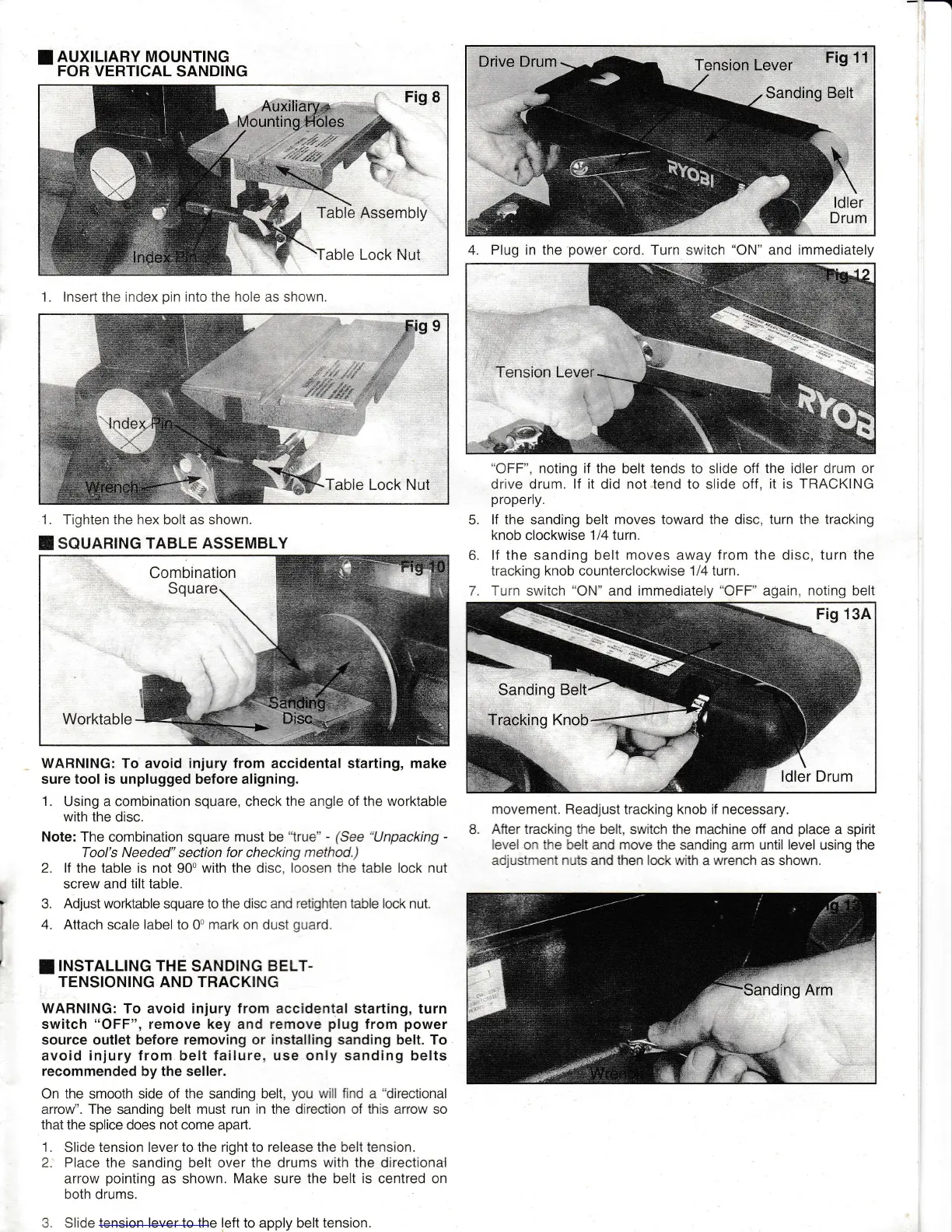
AUXTLTARY MOUNTTNG
FOR VERTICAL
SANDING
1. Tighten the hex bolt as shown"
I
souaRIruG TABLE ASSEMBLY
WABNING: To
avoid
injury from accidental starting, make
sure
tool is
unplugged
before aligning.
1.
Using a combination square, check
the
angle of
the worktable
with the
disc.
Note: The combination square must be
"true'
-
(See
Unpacking
-
Tool's Needed" section for checking
method.)
2.
lf
the table is not 90u with the disc,
loosen the table lock
nut
screw and
tilt table.
3.
Adjust
worktable square to
the
disc and
retighten table lock
nut.
4. Attach scale label to
0o
mark on dust
quard.
I
INSTALLING THE
SANDING
BELT-
TENSIONING AND TRACKING
WABNING: To
avoid
injury from accidental
starting, turn
switch
"OFF",
remove key
and
remove
plug
from
power
source outlet before
removing
or
installing sanding
belt. To
avoid iniury
from
belt
failure, use
only
sanding
belts
recommended
by the seller.
On the smooth side of
the
sanding
belt,
you
w
l f nd
a directional
arrow". The sanding belt must
run in
the directron of
this
arrow so
that the
splice does
not come apan.
1,
Slide tension lever to the
right
to
release
the
belt tension.
2. Place
the sanding belt over
the
drums
with the directional
arrow
pointing
as shown.
Make
sure the beit
is
centred on
both drums.
3.
Slide
tension lever
to
the left
to apply belt
tension.
tr
"OFF",
noting if the belt tends to slide off
the idler
drum
or
drive drum.
lf it
did not tend to slide off,
it is TRACKING
properly.
lf the sanding belt moves toward the disc,
turn the tracking
knob
clockwise
114 turn.
lf the sanding belt moves away
from
the disc,
turn the
tracking knob counterclockwise 1 l4 lurn.
Turn
switch
"ON"
and immediately
"OFF"
again, noting belt
movement. Readjust tracking knob if necessary.
B
After tracking the belt.
switch the machine off and
place
a spirit
leve on the belt and move the
sanding arm
until level
using the
adjustment nuts and then lock with
a
wrench as
shown.
6.
4. Plug in the
power
cord. Turn switch
"ON"
and immediately
1. lnsert the index
pin
into
the
hole
as shown

 Loading...