Operating manual
Rear disc mower with central suspension
- hydro-pneumatic or spring suspension
- 4 0 -
The load reducing chain is used to set a permanent height of the mower during operation. It
facilitates the correct positioning of the mower for operation and reduces the load on the tractor’s
hydraulic cylinder.
When connecting the mower to the tractor insert fitting A (Fig. 28a) of the chain onto the pin
B of the upper tie. Adjust the length of the chain for the mower in its working position at a height as
shown in Fig. 28b and also the tilt of the mower.
6.6. Adjusting cutterbar’s pressure on the ground by means of support
springs
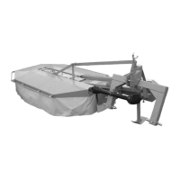
Pressure on the ground is adjusted by changing the tension force of support springs.
Decreasing the pressure of the cutterbar on the ground is done at the same time as increasing
the tension of the support springs by moving the lock in the next hole on the rod towards the springs
(Fig. 29). Increasing the cutterbar's pressure on the ground is caused by decreasing the tension of
support springs by moving the lock towards the rod's end.
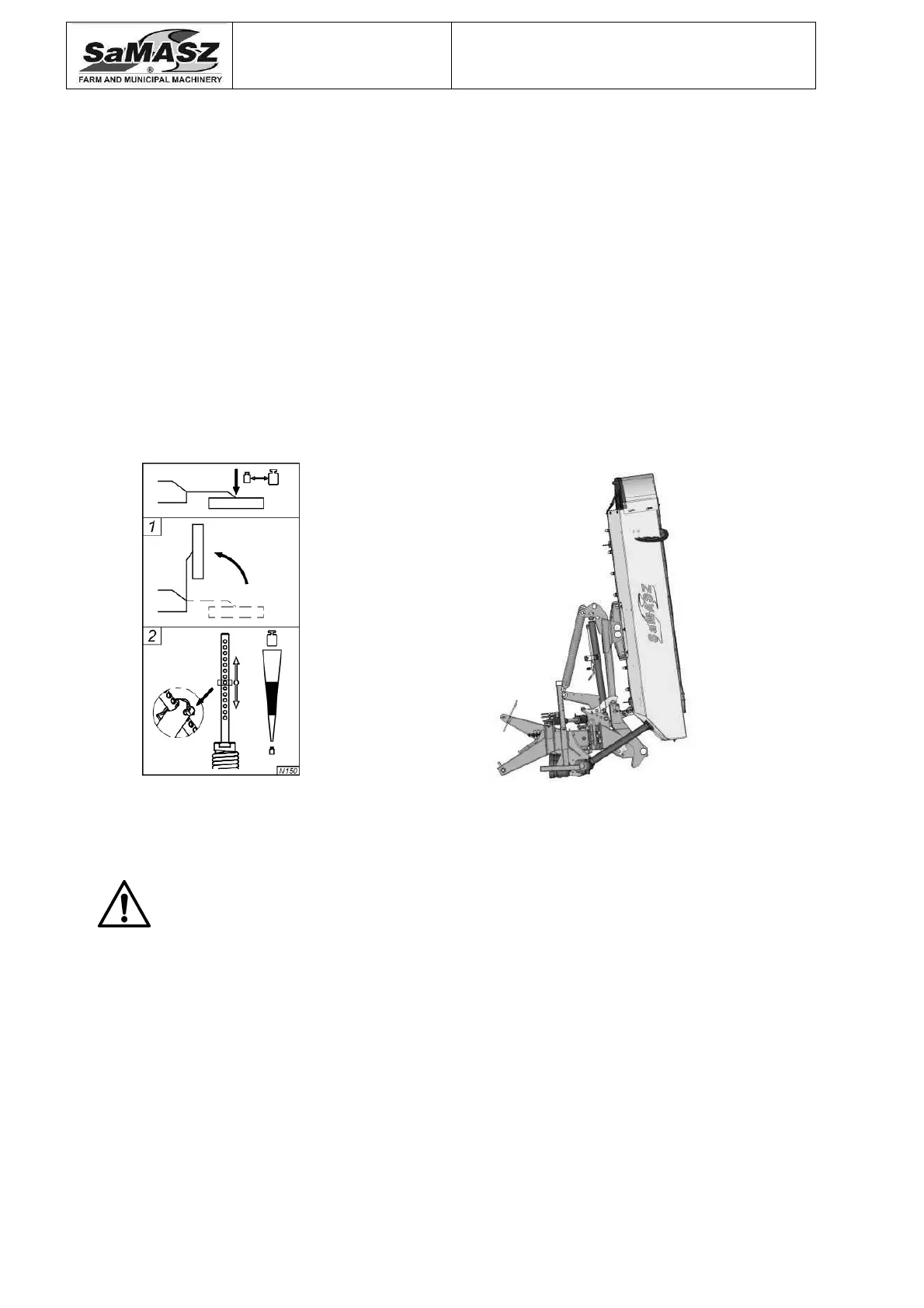
Adjustment may only be performed when the machine is in vertical position (Fig. 30).
Fig. 29. Adjustment of support springs Fig. 30. Mower in vertical position
WARNING:
Improperly relieved cutterbar will cause increase of its pressure on the
ground and thus lead to faster wear of sliding skids, overloading the
cutterbar, higher fuel consumption, damage to the stubble and contamination
of the fodder.
6.7. Adjustment of the clearance between the cover and the roller of the
conditioner
(For mowers:
KT 260 S (H), KT 300 S (H) and KT 261 S (H), KT 301 S (H))
Depending on the height and thickness of the grass being mowed, it may become necessary to
change the setting of the conditioner cover. The higher and thicker grass the larger the clearance
between the guard and the conditioner. The correct setting should be selected through trial and
error, so that the conditioner does not clog up and so that the overload clutch of the PTO shaft will
not activate. Adjustment of the conditioner guard is shown in Fig. 31.
 Loading...