EasyManua.ls Logo

S&C IntelliCap 2000 User Manual

S&C IntelliCap 2000
32 pages
To Next Page IconTo Next Page
To Previous Page IconTo Previous Page
Page #20 background imageLoading...
Page #20 background image
Some controls have var and/or neutral current or neutral voltage sensing connected in
the meter socket. Other controls use connector(s) on the bottom of the control enclosure,
or terminal block J6. See Figures 11 and 12 on page 12 and Figure 19 on page 17.
WARNING
Do not ground sensor cable shields at the top of the pole. Sensor cable shields
should be grounded only at the control end to prevent extraneous ground current
from flowing through the cable shields. This rule applies to all S&C connectorized
cables.
Voltage and Current
Sensing
A phase
Starpoint
To capacitor control
0-10 Vac
B phase
C phase
Neutral
Fuses
Switches
Neutral current sensor
(CT terminated on an
imbedded resistor)
The neutral voltage sensing option allows the capacitor control to monitor and
take action if it detects abnormal levels of voltage on the starpoint of an ungrounded
wye-connected bank. Use the information provided by the neutral voltage sensor manu-
facturer to design your installation. See Figure 23 on page 20.
Figure 22. Neutral current sensor installation between the starpoint and the neutral.
NOTICE
For neutral current sensing on 4-wire distribution systems where the starpoint
of the capacitor bank is tied to the neutral and/or ground, you must install the
neutral current sensor between the starpoint and the system neutral and/or ground.
See Figure 22.
Installing the Capacitor Control
20 S&C Instruction Sheet 1024-510
Question and Answer IconNeed help?

Do you have a question about the S&C IntelliCap 2000 and is the answer not in the manual?

S&C IntelliCap 2000 Specifications

General IconGeneral
BrandS&C
ModelIntelliCap 2000
CategoryController
LanguageEnglish

Summary

Introduction to IntelliCap 2000 Installation

Qualified Persons for Installation

Defines who is qualified to install, operate, and maintain the IntelliCap 2000 control.

Reading the Instruction Sheet

Emphasizes the importance of thoroughly reading this instruction sheet and related materials.

Retaining the Instruction Sheet

Instructs users to keep this instruction sheet as a permanent part of the control.

Proper Application Guidelines

Stresses selecting the equipment for a specific application within its rated limits.

Special Warranty Provisions

Outlines the standard warranty terms and conditions for the IntelliCap 2000 control.

Safety Information and Alerts

Understanding Safety Alert Messages

Explains the meaning of DANGER, WARNING, CAUTION, and NOTICE messages.

Following Safety Instructions

Advises contacting S&C for assistance if any part of the sheet is unclear.

Replacement Instructions and Labels

Guides on obtaining additional copies of the instruction sheet and replacing labels.

Essential Safety Precautions

Qualified Persons Access Restriction

Restricts access to the IntelliCap 2000 control solely to qualified personnel.

Adherence to Safety Procedures

Mandates following all safe operating procedures and company rules.

Personal Protective Equipment (PPE)

Stresses the use of appropriate PPE like gloves, hard hats, and safety glasses.

Safety Labels Management

Instructs users not to remove or obscure safety labels on the equipment.

Maintaining Safe Clearances

Emphasizes maintaining proper clearance from energized components during work.

Pre-Installation Setup and Checklist

Applicable Software Requirements

Details the required IntelliCap 2000 software version and system prerequisites.

Pre-Installation Checklist

Provides a step-by-step checklist for inspecting the control and verifying setup requirements.

Optional In-Shop Setup Steps

Describes optional configuration steps that can be performed before on-site installation.

Capacitor Control Installation Guide

Meter Base Mounting Procedure

Details how to correctly wire and mount the control on a meter base.

Bracket Mounting Methods

Explains mounting the control to a pole using straps or bolts.

Harness Wiring Connections

Guides on connecting the wiring harness for current and neutral sensing.

External Voltage Sensing Configuration

Details how to connect and configure external voltage sensing options.

Voltage and Current Sensing Methods

Describes neutral current and neutral voltage sensing installations.

Energize and Test the Control

Steps for putting the installed control into service and verifying its functions.

Connecting Communication Hardware

Instructions for connecting communication equipment like radios or Ethernet.

Front Panel Removal and Reinstallation

Ribbon Cable Handling During Removal

Cautionary advice on avoiding crimping the ribbon cable when removing/reinstalling the front panel.

Installation and Connection Diagrams

Standard Wiring Diagram

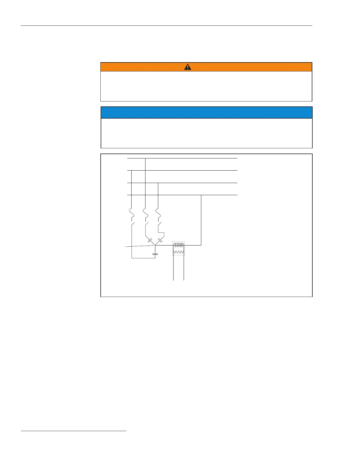
Provides the standard wiring diagram for the IntelliCap 2000 control.

WiFi, GPS, Door Sensor & Neutral Alarm LED Options

Illustrates wiring for optional communication and sensor modules.

4-Jaw Meterbase Options Wiring

Details wiring configurations for 4-jaw meterbase options (40, 41, 42).

6-Jaw Meterbase Options Wiring

Provides wiring details for various 6-jaw meterbase options (60-68).

K1 & M1 Options Wiring

Shows wiring configurations for K1 and M1 option modules.

M3 & M5 Options Wiring

Illustrates wiring for M3 and M5 option modules.

M7 & M11 Options Wiring

Details wiring configurations for M7 and M11 option modules.

Related product manuals