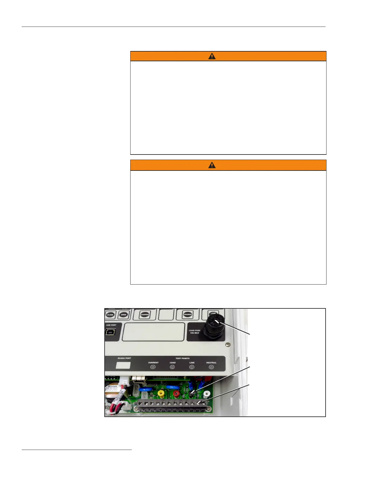
Figure 2. Load fuse on the faceplate.
Load fuse
Test points
Terminal strip
Installing the Capacitor Control
STEP 1. Read the following warnings before installing or operating this equipment:
WARNING
This control is connected to capacitors operating at primary voltage
levels. High voltage may be present in the wiring to the control or the
control itself during certain malfunctions of the capacitor bank wiring or
grounding system or due to a malfunction of the capacitor bank itself. For
this reason, access to the control should be treated with the same safety
precautions that would be applied when accessing other high-voltage
lines and equipment. Follow all locally approved safety procedures when
working on or around this control.
When open-circuited, current transformers can produce high voltages
that can result in injury or death. Proper shorting hardware and operating
procedures are required for safe operation. The current transformer must
be shorted before installing or removing the control. This control does
NOT provide for shorting of the current transformer.
WARNING
Do not energize the 110- to 240-Vac power source entering the control
enclosure until all wiring is complete.
Do not plug the sensor cable into the control until called for in the
instructions.
Do not enable communications by connecting radios, fiber-optic cables,
or dedicated phone lines until called for in the instructions.
Before attempting to access an existing installation, check carefully for
visible or audible signs of electrical or physical malfunction—do this
before touching or operating the control or any other part of the installation.
These warning signs include such things as smoke, fire, open fuses,
crackling noises, loud buzzing, etc. If a malfunction is suspected, treat
all components of the installation, including the control and associated
mounting hardware, as if they were elevated to primary (HIGH) voltage.
The sequence of installation steps outlined in this instruction sheet must
be followed to insure a safe and successful control installation.
STEP 2. Remove the 10-A load fuse near the lower right corner of the faceplate. See
Figure 2.
8 S&C Instruction Sheet 1024-510

 Loading...