Most communication equipment can be mounted inside the capacitor control enclosure
(in the door). This eliminates clutter and provides better reliability for the installation.
Depending on the location of the capacitor bank site, you may also need one or more
repeater radios to enable communication between this control and the SCADA master
station.
For more information, see Instruction Sheet 1024-561, “IntelliCap 2000 Automatic
Capacitor Control: DNP Points List and Implementation,” or contact your local S&C
Sales Office.
All IntelliCap 2000 controls are radio-ready. This gives you the flexibility to add
communication hardware later. Serial and Ethernet connectors are provided.
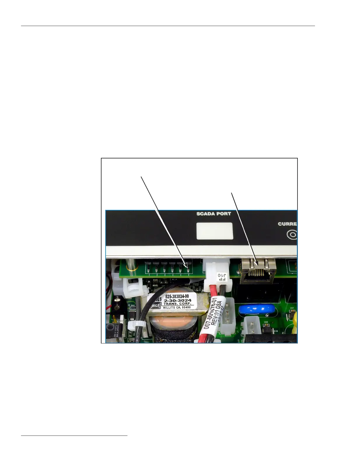
The SCADA PORT connector provides a data and power (12-Vdc) connection for the
radio. Wiring for the six-pin IDC 0.156-inch header in the control is shown in Figure 25.
The cable from the radio is terminated with an ITW MAS-CON 0.156-inch center line IDC
connector (or equivalent).
Connecting
Communication
Hardware
Figure 25. Ethernet Port and pinout for the SCADA PORT.
Installing the Capacitor Control
SCADA
PORT:
Pin 1 +12 Vdc
Pin 2 CTS
Pin 3 TXD
Pin 4 RTS
Pin 5 RXD
Pin 6 GND
Ethernet Port
24 S&C Instruction Sheet 1024-510

 Loading...