Parking
brake lamp
Parking brake
switch
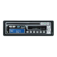
Close the self-lock
connector securely.
Parking brake signal line
Put it into the self-lock connector
Self-lock
connector
Parking brake connector cable
Insert the cable end into the self-lock connector.
When you connect the parking brake connector cable, set the parking brake and stop the engine.
Car may move and an accident may result.
t CAUTION
¡The TV/video signals appear only after you park the car and set the parking brake. When the car starts
moving, the TV/ video signals automatically disappear for safety reasons.
¡If the parking brake signal line is too thin, connect the parking brake connector cable to the parking brake
signal line directly without using the self-lock connector.
¡After finish attachment and connection, please check whether brake lamps, back lamps, horn, and blinkers
operate correctly.
Hint
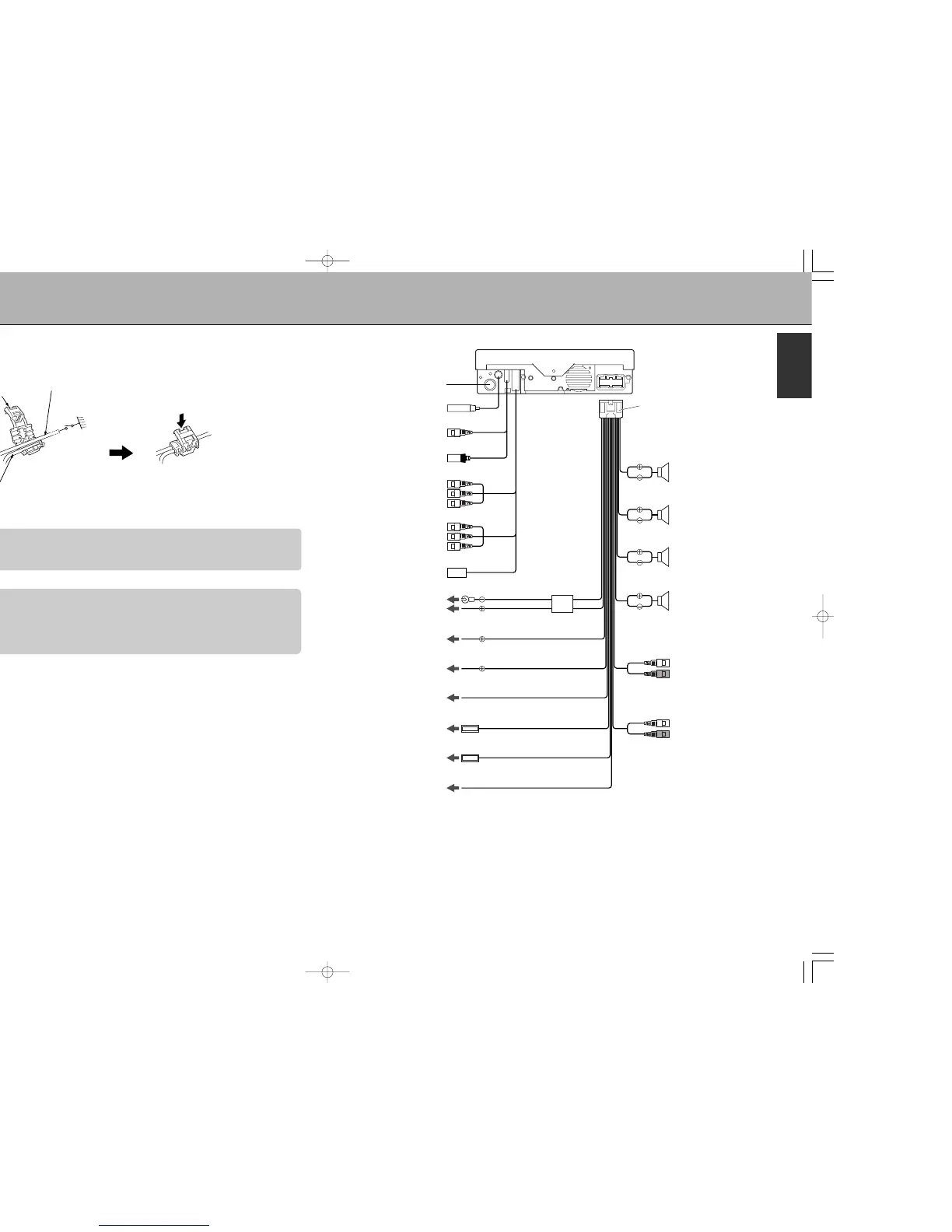
CONNECTION (1)
*1. First connect the black ground lead, then connect the yellow and red power input leads.
*2. Depending on what antenna you are using, connect either to the control terminal of the motor aerial, or to the power
terminal for the booster amplifier of the film-type antenna.
Note:
If there is no accessory position (ignition ACC 12 V red wire), connect to the +12 V power (continuous 12 V
yellow wire) terminal which is energized at all times.
 Loading...