- 4 -
TAPE ADJUSTMENTS
1. HEAD REPLACEMENT AND AZIMUTH ADJUSTMENT
(1) Head replacement
1. After replacement, demagnetize the heads by using a
degausser.
2. Be sure to clean the heads before attempting to make any
adjustments.
3. Be sure both channels (1 and 2) are the same level.
(Using a dual-channels oscilloscope).
4. All wiring should be returned to the original position after
work is completed.
Adjustment Item Test Tape Measuring Output connection Adjust Adjust
Instrument location value
(a) HEAD AZIMUTH VTT738 etc. AC-voltmeter SPEAKER TERMINAL HEAD AZIMUTH Max.
DECK "A" (10KHz) SCREW
(b) HEAD AZIMUTH VTT738 etc. AC-voltmeter SPEAKER TERMINAL HEAD AZIMUTH Max.
DECK "B" (10KHz) SCREW
(c) MOTOR SPEED MTT-111 FREQUENCY SPEAKER TERMINAL VR311 3,000Hz
(NORMAL) (3,000Hz) COUNTER
• After making the adjustment, secure the azimuth
adjustment screw by applying screw lock (TB-1401B).
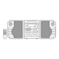
(2) Head azimuth
• DECK "A"
1. Load a test tape (VTT-738,etc.: 10kHz) for azimuth
adjustment.
2. Press the PLAY button.
3. Use a flat-tip (-) screwdriver to turn the screw for normal
azimuth adjustment so that the left and right outputs are
maximized at the same phase during normal playback.
4. Press the STOP button.
• DECK "B"
1. Load a test for azimuth adjustment.
2. Press the PLAY button.
3. Azimuth screw adjustment.
4. Press the STOP button.
TAPE "A"
REVERSE
NORMAL
TAPE "B"
REVERSE
NORMAL
YELLOW
ORANGE
RED
WHITE
YELLOW
RED
EARTH
EARTH
WHITE
TAPE ’’A’’
PLAY HEAD
TAPE ’’B’’
R/P HEAD
E. HEAD
 Loading...


