CD ADJUSTMENT
Electrical Adjustment
10K
So
far we have presented explanations regarding compact disc
player handling, notes prior to
repair, handling the pick-up and
disassembly of the unit. Be sure to carefully read these
‘r;::D–A*’’O-’cO”
instructions before making any adjustments.
BAND PASS FILTER
Preparations for Adjustments
Measuring instruments, tools and filter
(4) Oscillator (400 Hz, 300mV RMS)
(1) Test disc. : YEDS lB (Sony)
(5) Frequency Counter (5MHz; or more)
(2) Oscilloscope: SS5711 (IOMHZ or dual phenomenon)
(6) Screw drivers (non-metalic) for adjustments
or Memoryscope : DSS6521 (Storagescope)
(7) Band Pass Filter
(3) Digital voltmeter (Input impedance 1M ohm or more)
(B) AC Voltage Meter
Notes : a. The adjustments can be using the equipment produced by other manufactures provided that the performance of that
equipment corresponds to that of the above listed models.
b. Use a 10:1 probe for observing signals on the oscilloscope and stora9e scoPe.
c. Test disc is subject change without notice.
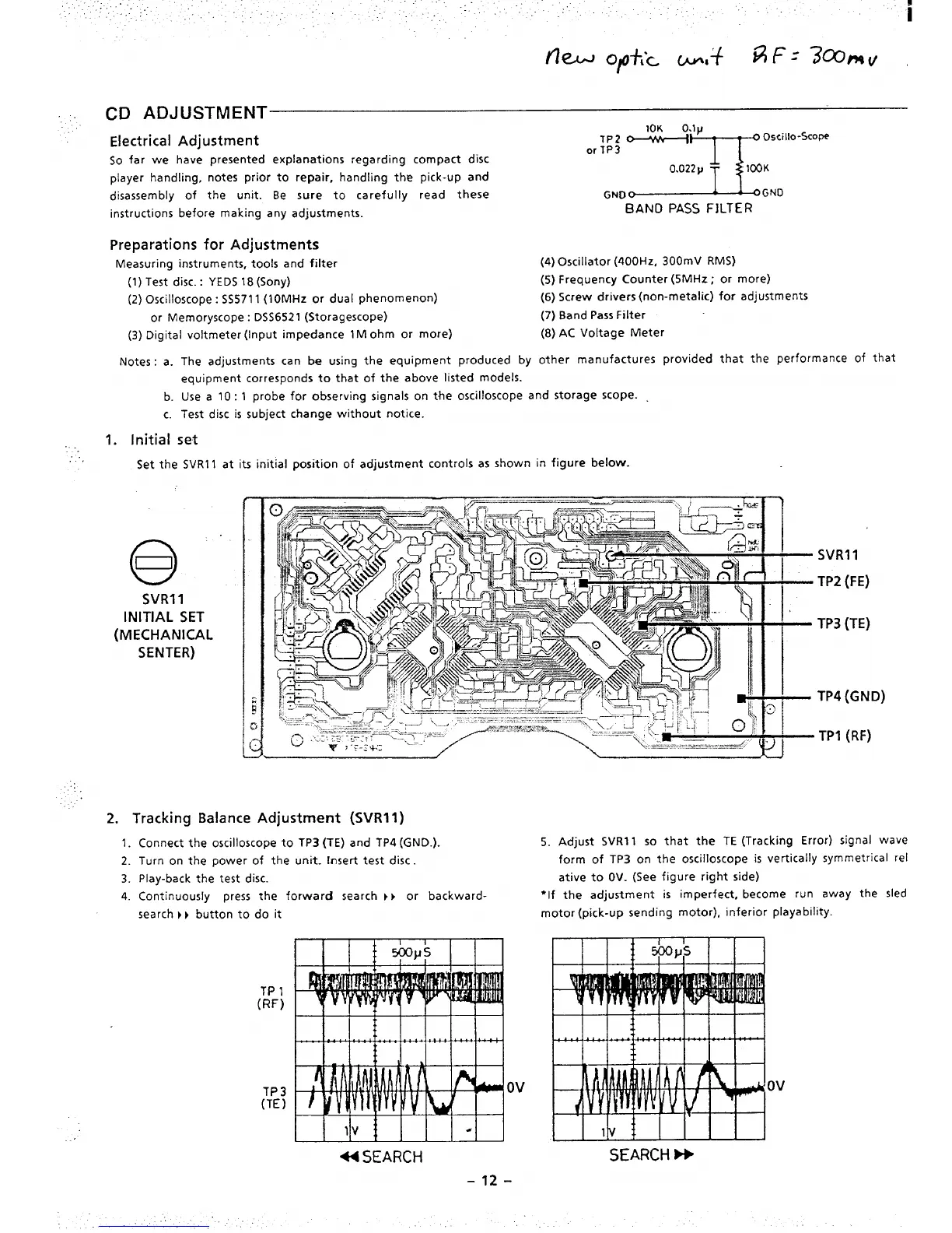
1. Initial set
.,
Set the SVR11 at its initial position of adjustment controls as shown in figure below.
SVR11
INITIAL SET
(MECHANICAL
SENTER)
..
2. Tracking Balance Adjustment (SVRII)
1.
2.
3.
4.
Connect the oscilloscope to TP3 (TE) and TP4 (GND.).
Turn on the power of the unit.
Insert test disc.
Play-back the test disc.
Continuously press the forward search } } or backward-
search } } button to do it
TP 1
(RF)
TP3
(TE)
Ov
-SEARCH
-12-
SVRI 1
TP2 (FE)
TP3 (TE)
TP4 (GND)
TPI (RF)
5.
Adjust SVR11 so that the TE (Tracking Error) signal wave
form of TP3 on the oscilloscope is vertically symmetrical rel
ative to OV. (See figure right side)
“If the adjustment is imperfect, become run away the sled
motor (pick-up sending motor), inferior playability.
Ov
SEARCH h

 Loading...


