, ., MECHANISM REMOVAL (CD)
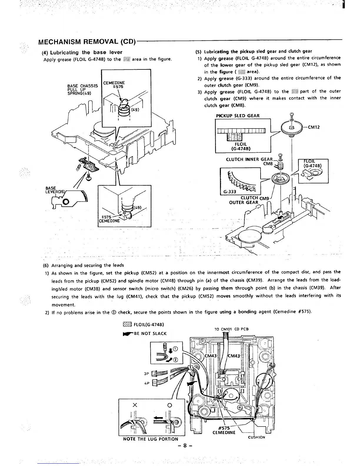
(4) Lubricating the base lever
Apply grease (FLOIL G-474B)to the >~area in the figure.
.....
(6)
1)
2)
I
I
.
.
--
Arranging and securing the leads
—.
(5)
1)
2)
3)
Lubricating the pickup sled gear and clutch gear
ApplY grease (FLOIL G-474B) around the entire circumference
of the lower gear of
the pickup sled gear (CM12), as shown
in the figure ( % area).
Apply grease (G-333) around the entire circumference of the
outer ctutch gear (CM9).
Apply grease (FLOIL G-474B) to the * Part of the outer
clutch gear (CM9) where it makes contact with the inner
clutch gear (cM8).
PKKUP SLED GEAR
F~+-cM12
. ..—
OUTER GEAR “-”h ]’
.\.. ..
As shown in the figure, set the pickup (CM52) at a position on the innermost circumference of the compact disc, and pass the
leads from the pickup (CM52) and spindle motor (CM48) through pin (a) of the chassis (CM39). Arrange the leads from the load-
ing/sled motor (CM38) and sensor switch (micro switch) (CM26) by passing them through point (b) in the chassis (CM39). After
securing the leads with the lug (CM41), check that the pickup (CM52) moves smoothly without the leads interfering with its
movement.
if no problems arise in the @ check, secure the points shown in the figure
using a bonding agent (Cemedine #575).
TO CN101 CD PCB
~BE NOT SLACK
m.
NOTE THE LUG PORTION
-8-
CU\HION

 Loading...


