-19-
G-Polarized Glass
Mounting Base
R-Polarized Glass
Mounting Base
B-Polarized Glass
Mounting Base
A
A
A
Fig.1-2
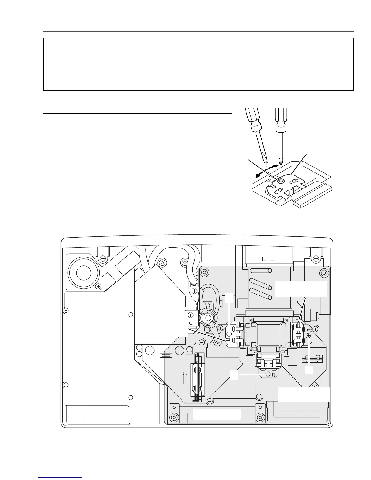
■ Optical Adjustments
Main Board
Before taking optical adjustments below, remove the Cabinet Top and Main Board following to the “Mechanical
Disassemblies”
Adjustments require a plus screwdriver, 2.0mm hex wrench and a slot screwdriver.
Note: Do not disconnect connectors K8A, K8B, K8H, K48K, K48L, K66A, K66B, K66C, K66D, K66E and K66F
on the main board, because the projector can not turn on due to operate the power failure protection.
Fig.1-1
Polarized
glass
mounting base
A
[Before Adjustment]
- Input a 100% of black raster signal.
[R/G/B-CONTRAST ADJUSTMENT]
1 Loosen a screw A (Fig.1-1/1-2) on the polarized glass mounting
base which you intend to adjust.
2 Tu rn the polarized glass mounting base as shown in Fig.1-1 to
obtain the darkest brightness on the screen.
3 Tighten the screw A to fix the polarized glass mounting base.
Repeat steps 1 to 3 for remaining polarized glasses.
Contrast adjustment
 Loading...