Self-Proving Vehicle Grounding Verication System
General
Page 5.
1.1 Purpose Of Equipment
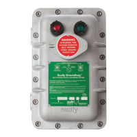
The ST-47 Groundhog is a line powered, Self- Proving, Vehicle Ground Verication System. It may
be used to insure a safe ground between a terminal loading rack and a tank vehicle which is in the
process of loading or unloading a hazardous product. The Groundhog system can be used in one
of three modes: 1.) Wire-Through, 2.) Stand -Alone, 3.) Non Self-Proving. Optional front cover
lamps indicate grounded (green lamp on) or non-grounded (red lamp on) status. Intrinsically safe
ground verication signals connect to TB2 terminals 2 (ground) and 3 (proving signal) in modes 1
and 2. Refer to Figure 1.2 for ST-47 Terminal Block (TB) locations.
1.1.1 Wire-Through Mode Description
In the Wire-Through conguration, the ST-47 control monitor is ideally mounted near a new, or
existing, Scully overll prevention monitor (see Appendix for appropriate interconnection wiring
diagram). When the two monitors are located in close proximity, vehicle drivers or loader personnel
can easily view the status lamps.
Two wires from the ST-47 I.S. terminals connect to the new, or existing, overll prevention cable
junction box. A single Scully Ground Bolt, mounted on a tank vehicle (or other container), serves as
the truck ground verication point. The system is self-proving when the overll prevention plug is
connected to the vehicle mounted Ground Bolt (P/N 08560) through socket pin no. 9.
A time-varying intrinsically safe voltage is sent out on ST-47 TB2 terminal 3. With the Scully overll
protection plug connected to the vehicle mounted overll system socket, a ground connection is
established through pin 10 of the socket to the chassis of the vehicle. The ground proving signal
enters the socket through pin 9. The Ground Bolt is required to complete the circuit in the ST-47
controller. The circuit is completed through pin 9, through the green wire, through the Ground Bolt,
to the chassis of the vehicle or equipment, through pin 10 and back to the ground connection, TB2
terminal, at the controller. If the control monitor senses a complete signal path, it will close its
“permissive” contact. The permissive contact is typically used to control a pump, valve, or input to
a Terminal Automation System or Programmable Logic Controller (PLC).
1.1.2 Stand Alone Mode Description
Used in the Stand-Alone mode, the ST-47 Groundhog is typically mounted near the terminal rack
equipment and hard wires to the Scully Model SC-47CC or SC-47CC/D cable junction box. The
cable junction box contains terminals connecting to a special snap-on plug using a 32 foot (ten
meter) coiled or a 20 foot (six meter) straight cable. A single Scully Ground Ball mounted on a tank
vehicle serves as the truck ground verication point. The system is self-proving when the snap-on
plug is connected to the vehicle mounted Ground Ball. When connected, the ST-47 sends a
time-varying intrinsically safe voltage from TB2 terminal 3 to the top of the two piece Ground Ball
and through the frame of the vehicle. The ball returns a portion of the signal to the control monitor
TB2 terminal 2 through its base. If the control monitor senses this signal, it will close its
“permissive” contact. The permissive contact is typically used to control a pump, valve, or input
to a Terminal Automation System.