47
LC-24LE210
LC-24LE220
IMPORTANT SAFETY NOTICE:
PARTS MARKED WITH “ ” ( )
ARE
IMPORTANT FOR MAINTAINING THE SAFETY OF
THE SET. BE SURE TO REPLACE THESE PARTS
WITH SPECIFIED ONES FOR MAINTAINING THE
SAFETY AND PERFORMANCE OF THE SET.
SCHEMATIC DIAGRAMS
Description:
VOLTAGE MEASUREMENT CONDITION:
1. The voltages at test points are measured on the stable supply voltage of AC 230V. Signals are fed by a color bar
signal generator for servicing purpose and the above voltages are measured with a 20k ohm/V tester.
INDICATION OF RESISTOR & CAPACITOR:
RESISTOR
1. The unit of resistance “Ω ” is omitted. (K=kΩ=1000 Ω, M=MΩ).
2. All resistors are ± 5%, unless otherwise noted. (J= ± 5%, F= ± 1%, D= ± 0.5%)
3. All resistors are 1/16W, unless otherwise noted.
4. All resistors are Carbon type, unless otherwise noted.
C : Solid W : Cement
S : Oxide Film T : Special
N : Metal Coating
CAPACITOR
1. All capacitors are μF, unless otherwise noted. (P=pF=μμ F).
2. All capacitors are 50V, unless otherwise noted.
3. All capacitors are Ceramic type, unless otherwise noted.
(ML): Mylar (TA): Tantalum
(PF): Polypro Film (ST): Styrol
CAUTION:
This circuit diagram is original one, therefore there may be a
slight difference from yours.
!
1
I
H
G
F
E
D
C
B
A
2
3
4567
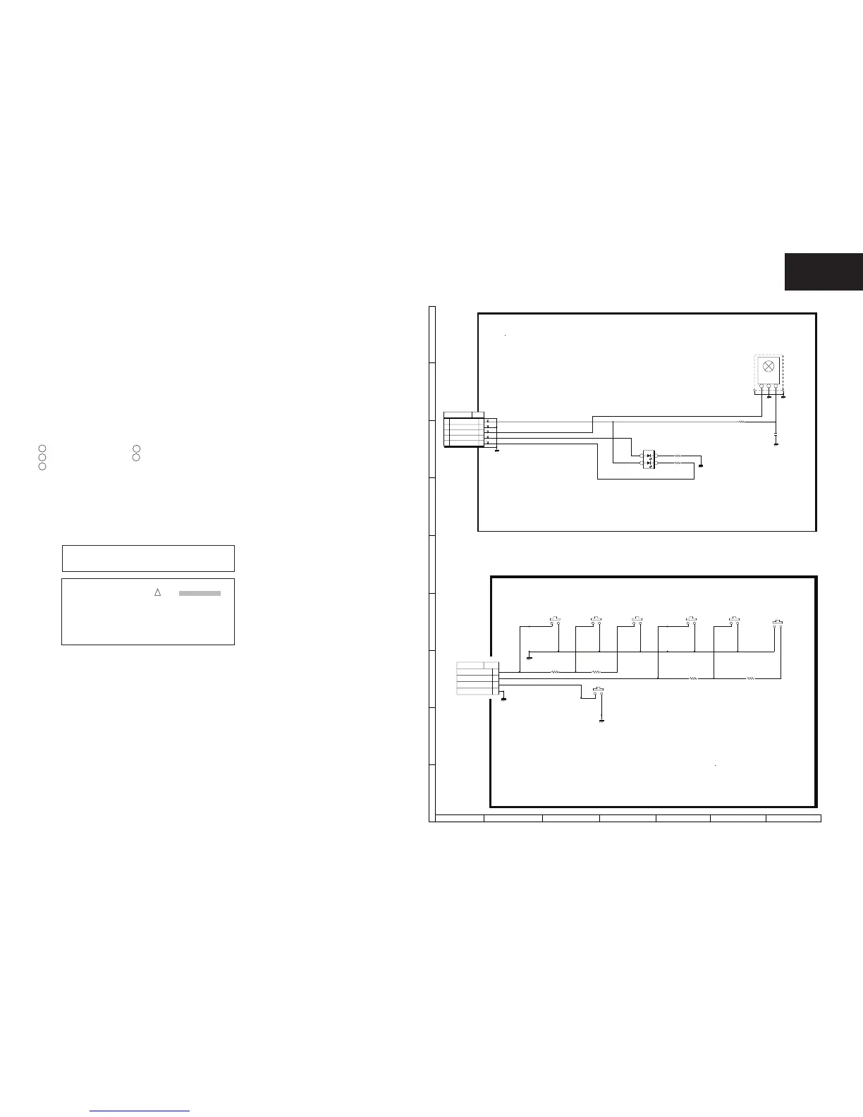
LED Unit Diagram DUNTKF640WE
KEY Unit Diagram DUNTKF534WE02
ZZ (18.05.2010)
BU+3.3V
C5102
10u
16V
R5109
100
R5108
120
R5101
100
TL101
TL102
TL103
TL104
TL105
*P5101
TO MAIN
1
BU+3.3V
2
GND
3
R/C
4
LED BLUE
5
LED RED
D5103
SML522BUW
1
2
RED
3
4
BLUE
SLD5101
PA076WJFW
RMC5101
UA053WJ
IR RECEIVER MODULE
1
OUT
2
GND
3
VCC
 Loading...