11. SITE INSPECTION VM-5S
-81-
(3) Verification of set values
The trigger level set value, hysteresis set value, and speed relay set value are preset prior to
shipment. To change any of these values, refer to 7. PARAMETER SETTING on page 25.
(4) Dummy Input Verification
Apply a dummy signal from an oscillator to CH1 and CH2, and verify SPEED RELAY
operation.
11-2 VERIFICATION IN TURNING CONDITION
(1) Adjustment of Trigger Level and Hysteresis
Check the monitor output and pulse output in turning condition, and verify that the set values
are appropriate (refer to 7. PARAMETER SETTING on page 26).
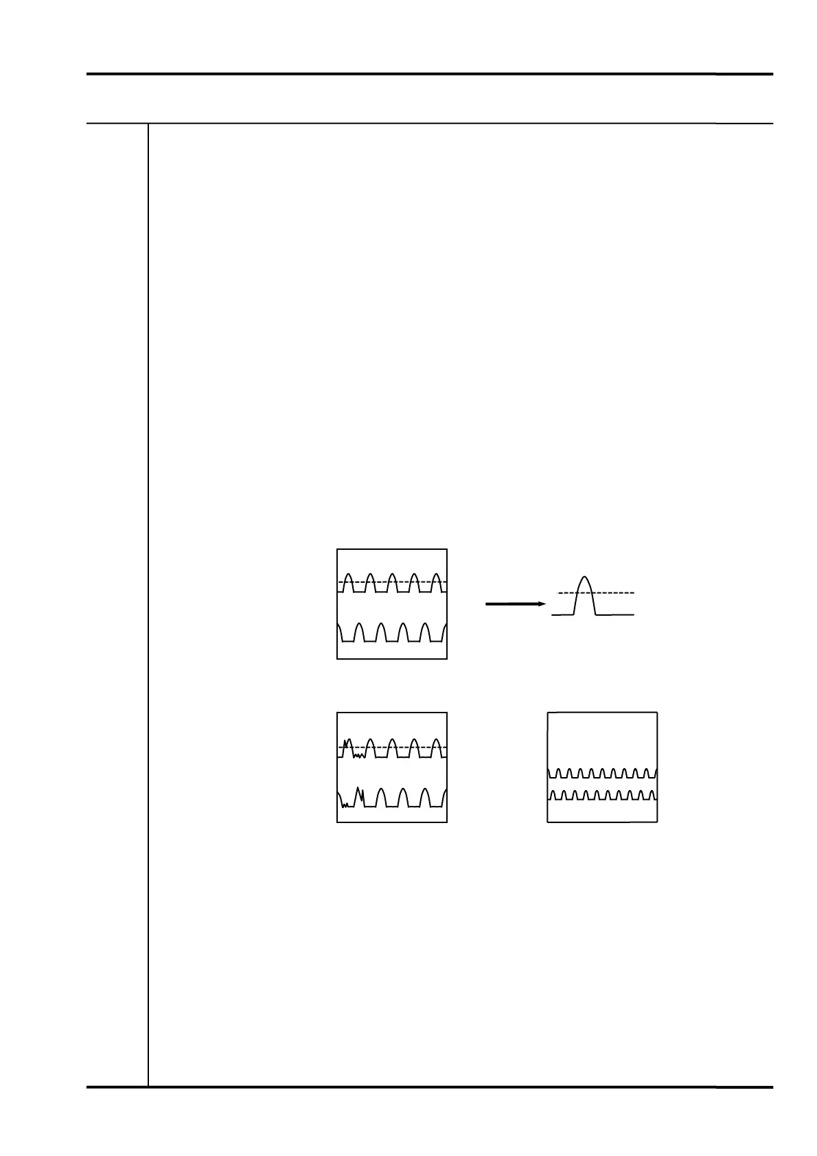
Also carefully check the signal waveform for noise components (magnetic noise, runout, etc.).
If the noise level is such that it cannot be eliminated by adjusting the hysteresis, noise
countermeasures such as installing a surge killer will be required.
Wave form Examples
CH2 0V
CH1 0V
CH1
CH2
CH2 0V
CH1 0V
CH2
CH1
CH2 0V
CH1 0V
CH1
CH2
↕5
Detail
-15V
-21V
Good waveform
Bad waveform1 Bad waveform2
Noise mixed in
↕5 ↕5
Set gap voltage at highest
point of target is too low.
 Loading...