Chapter 4 Technical Information
TiM55x/56x/57x ranging laser scanner
14 © SICK AG · Germany · All rights reserved · Subject to change without notice 8015883/YZK8/2016-07-07
Electrical installation
4 Electrical installation
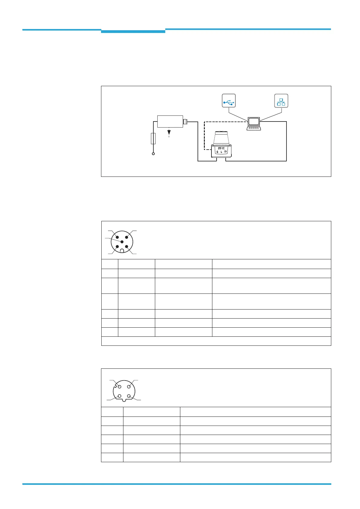
4.1 Overview of all interfaces
4.2 Pin and wire color assignments
"Power/Out" connection (plug, M12, 5-pin, A-coded)
"Ethernet" connection (socket, M12, 4-pin, D-coded), for adapter cable No. 6034415
Pin Signal Color of wire Function
1 DC 9 V ...28 V Brown Supply voltage
2SYNC/DEVICE
READY
White Synchronization output (SYNC/Device Ready)
3GND
Blue
Ground
4N.c. – –
5N.c. –
– – Metal Shield
Do not connect reserved pins!
Pin Signal Funktion
1 TD+ (Ethernet) Transmitter+
2 RD+ (Ethernet) Receiver+
3 TD– (Ethernet) Transmitter–
4 RD– (Ethernet) Receiver–
–– Shield
SOPASSOPAS
"Power/Out"
"USB 2.0"
Configuration
Diagnosis
TiM
Connection
box
Driver for request of
measurement values
and further data
processing
SYNC/
Device Ready
"Ethernet"
DC 9 ... 28 V
delay-
action
fuse
0,8A/T
USBUSB
EthernetEthernet
1
43
5
2
 Loading...