Technical Information Chapter 4
TiM55x/56x/57x
Electrical installation
8015883/YZK8/2016-07-07 © SICK AG · Germany · All rights reserved · Subject to change without notice 19
4.5 Installation steps
4.5.1 Supply voltage connection
The TiM5xx requires a supply voltage between DC 9 and 28 V (stabilized protective extra-
low voltage [SELV] as per the IEC 60364-4-41 standard) .
The electricity source must be able to provide a power of 5 W at minimum.
Risk of injury due to electrical current!
If the supply voltage is generated by extracting and converting current from the alternating
current network using a stabilized power supply unit, insufficient electrical separation be-
tween the input and output circuit may lead to an electric shock.
Only use a power supply unit whose output circuit has reliable electrical separation due
to double insulation and a safety transformer as per IEC 742.
Risque de blessure dû au courant électrique !
Une séparation électrique insuffisante entre les circuits d’entrée et de sortie peut provo-
quer une électrocution si la tension d’alimentation est générée par le prélèvement et la
conversion de courant du réseau alternatif à l’aide d’un bloc d’alimentation stabilisé.
N’utiliser qu’un seul bloc d’alimentation dont le circuit de sortie, à l’opposé du circuit
d’entrée, possède une séparation électrique sécurisée par une double isolation et un
transformateur de sécurité selon CEI 742 (VDE 0551).
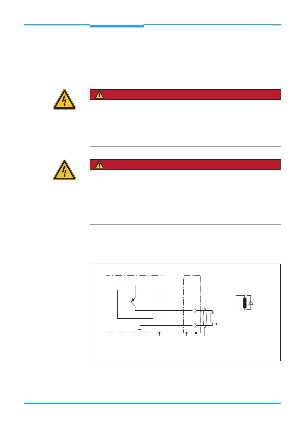
4.5.2 Wiring of output SYNC/DEVICE READY
Output SYNC/DEVICE READY is used to output the Device Ready signal, an error and a reg-
ular index pulse.
TiM5xx
V
S
= DC 9 V ... 28 V
SYNC/
DEVICE
READY
Structure and wiring principle of output SYNC/DEVICE
READY (pin 2)
2
5
GND
V
out
Quenching circuit:
Install an anti-surge
diode directly at the
load!
For inductive load:

 Loading...