Technical Information Chapter 4
TiM55x/56x/57x
Electrical installation
8015883/YZK8/2016-07-07 © SICK AG · Germany · All rights reserved · Subject to change without notice 15
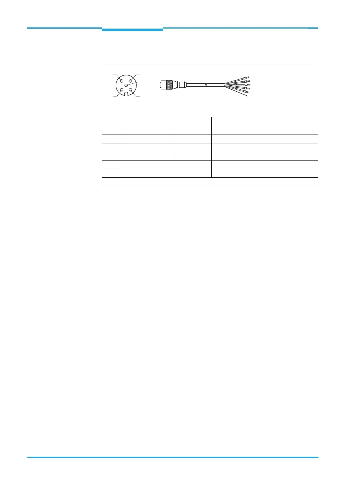
4.2.1 Optional accessory: adapter cabe No. 6036159 with socket, M12, 5-pin, A-
coded and open end
4.3 Notes on electrical installation
When the cover of the USB socket is open or the USB cable is connected, the TiM5xx
must not come into contact with moisture and dust. In this status, the TiM5xx does not
correspond to any specified IP enclosure rating.
Use the supplied seal for the USB connection to prevent contact with moisture and dirt.
When operating the USB interface, ESD/EMC interferences can lead to an interruption
of the USB connection. To continue with the data transfer, disconnect the USB cable
from the TiM5xx and reattach it to establish contact. To re-establish communication
between TiM5xx and PC, select C
OMMUNICATION > GO ONLINE in the SOPAS configuration
software.
Electrical connections between the TiM5xx and other devices may only be connected
or disconnected when the system is not live, otherwise the devices may be damaged.
All connection cables on the TiM5xx may not exceed a length of 3 m (9.84 ft) in order
to ensure that it conforms with the CE.
Conducting cross sections of the supply cable from the customer's power system
should be selected and perform in accordance with the applicable standards.
Protected the TiM5xx with an external 0.8 A delay-action fuse at the start of the supply
cable from the point of view of the power supply.
All electrical circuits connected to the TiM5xx must be designed as SELV or PELV elec-
tric circuits (SELV = Safety Extra Low Voltage, PELV = Protective Extra Low Voltage).
When setting up a startup device with a 5-pin M12 male connector, do not wire the re-
served pins (e.g. as solder post)!
Do not switch on the supply voltage for the TiM5xx until the connection work has been
completed and wiring work has been checked carefully.
Pin Signal Color of wire Function
1 DC 9 V ... 28 V Brown Supply voltage
2 SYNC/DEVICE READY White Synchronization output (SYNC/Device Ready)
3GND Blue Ground
4N.c. – –
5N.c. – –
– – Metal Shield
Do not connect reserved pins!
Socket, M12, 5-pin, A-coded
(front view)
Illustration may differ
1
43
5
2
 Loading...