Ethernet switch in the Ethernet network
4
19 | 34
Building Technologies
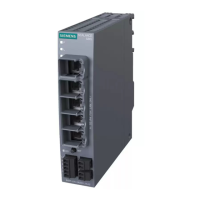
4.5 Ethernet switch in the Ethernet network
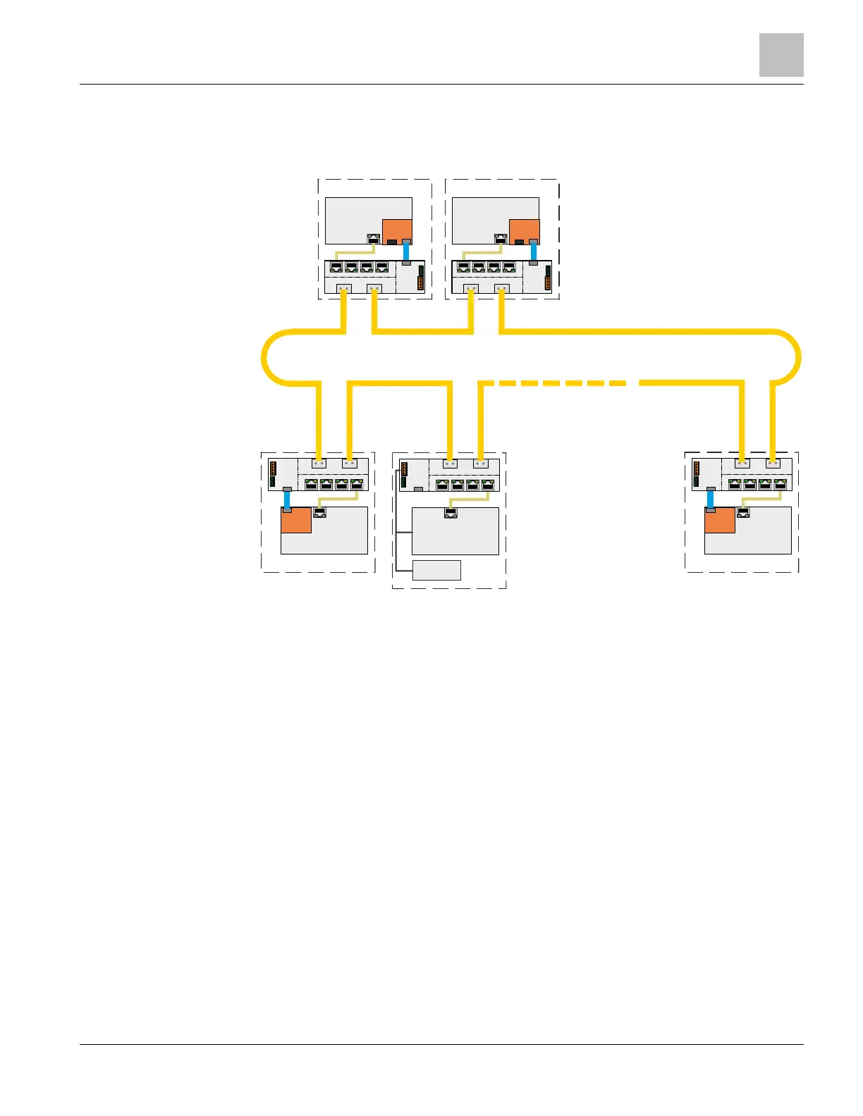
The basic circuit diagram below shows the possible applications of the Ethernet switch
in a redundant Ethernet ring network.
Figure 12: Ethernet switch in a redundant Ethernet ring network
There are 3 types of Ethernet ring wiring, depending on the Ethernet module in use:
● Electric Ethernet with copper wiring via 10/100BaseT connections (RJ-45
connector) with a VN2001 module – max. 330 ft/100 m long
● Optical Ethernet with a fiber-optic 100BaseFX connection in multi-mode version
with a VN2002 module – max. 13100 ft/4 km long
● Optical Ethernet with a fiber-optic 100BaseFX connection in single-mode version
with a VN2003 module – max. 131000 ft/40 km long
The type of ring wiring between each switch is independent and can be selected at will.
A maximum of 32 switches are allowed for each Ethernet ring.
The switch built into an FS20 panel is supplied via the MoNetBus from the
PMI & mainboard. If the switch is built into another housing or device, it is supplied with
power via a 24 V current-limited and supervised power supply that has been approved
for use in fire detection.
MoN et
PMI & Mainboard
Ethernet
Panel
Switch1
P2 P3 P4 P5
P0
P1
POWER
FAULT
MoNet
Ethernet
Switch2
P2 P3 P4
P0
P1
MoNet
Optical or electrical Ethernet Ring
MMS
24V supply
P
Ethernet
Panel
P2 P3 P 4 P 5
P0 P1
POWER FAULT
SA
P
Ethern et
P2 P3 P 4 P5
P0 P1
SA
Switch3 Switch4

 Loading...