7
27 | 34
Building Technologies
7 Indicators
LED Color Function Condition Meaning
PWR Green Power LED Lit up ● Normal operation
Not lit up ● No power supply
FAULT Yellow General fault See separate FAULT LED table
RM Green Redundancy manager See separate RM LED table
PD Green Not connected -- No function
-- No function
P2 Green/yellow Ethernet status LEDs Green ON ● Link up
P3 Green OFF ● Link down
P4 Yellow flashing ● Data communication active
P5 Yellow does not light
up
● No data communication
Table 1: Status LED
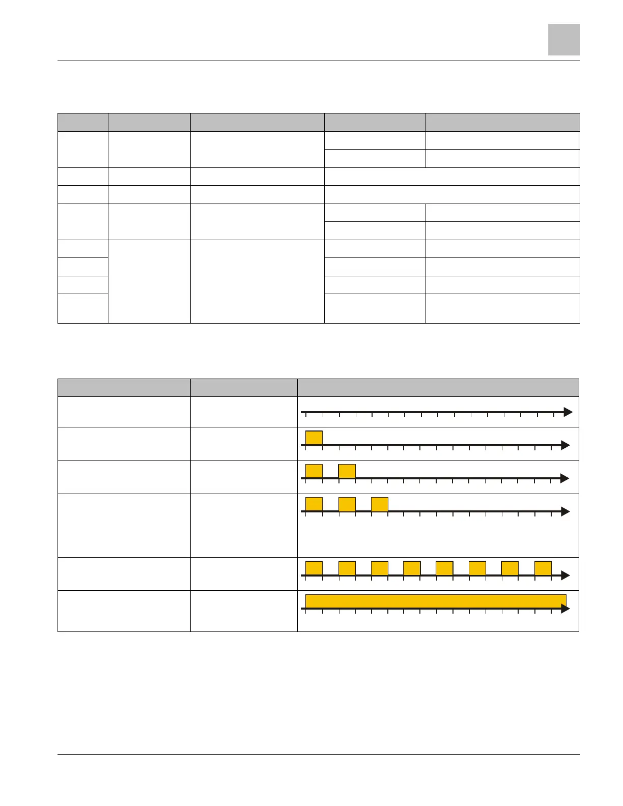
Function indicators for the FAULT LED
Function indicator Meaning FAULT LED flashing pattern (every 2 s)
Normal Operation Normal operation
FW Update Mode Ready for firmware
update
FW Update Running Ethernet switch is
loading firmware
FW Update Failed FW update could not
be completed,
network connection
may have been
interrupted
Checksum Failed Incorrect firmware
checksum
Fatal FAULT Ethernet switch is
generating some
other fault
Table 2: FAULT LED flashing pattern
 Loading...