802-9081.9 • INSTALLATION AND OPERATING INSTRUCTIONS • NXPLUS C • Revision 11 111/293
Installation
15.4 Assembling the busbars
The components of the busbars are delivered separately with the accessories.
• To simplify installation, remove pre-assembled low-voltage compartments, if required.
• Before assembling the busbars, all panels must have been bolted together (see page 108,
"Aligning and joining the panels").
• Remove any current transformers pre-assembled on the busbar (for 1250 A busbar system).
• Current transformers in oval design for the twin busbar system can remain mounted.
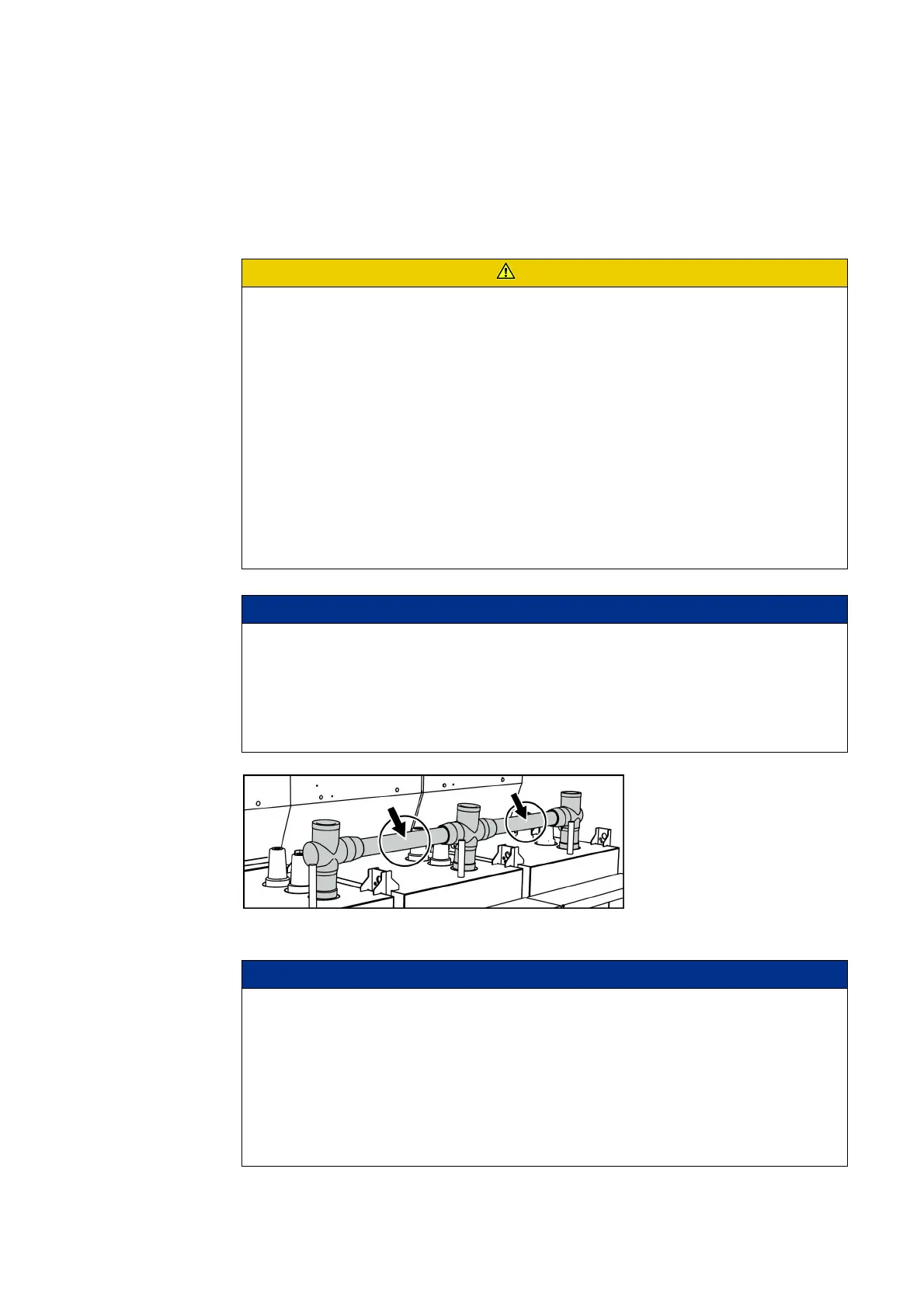
Fig. 68: Comparing manufacturer imprint of busbars
CAUTION
Flashovers due to insufficient electrical contact, or pollution of the push-on surfaces
Damage to the busbars during operation.
➭ All busbar assembly work must be carried out with particular care.
➭ Check the contact surfaces and the silicone surfaces for damages before assembly.
➭ Observe extreme cleanliness.
➭ No smoking.
➭ Do not unpack busbars, cross adapters and end adapters until right before assembly.
➭ Brush oxidized copper surfaces bright, clean and grease them with the supplied mounting
paste before connection.
➭ Use the supplied mounting paste only.
➭ Tighten all bolted joints with correct torque. On all bolted joints, execute a torque test with
the torque wrench. Afterwards, mark the bolted joints on the nut with a waterproof pen
(perform this step only after consultation with the switchgear operator).
NOTICE
Busbars from different manufacturers
For the combination of busbars from different manufacturers, no responsibility is
assumed.
➭ Within one switchgear assembly, do only install busbars from a single manufacturer; if
necessary, contact the Siemens Hotline.
➭ Compare the manufacturers by means of the imprint on the busbars.
NOTICE
Damage to the auxiliary switch at the three-position disconnector
Can cause incorrect electrical position indications.
The load can deform the mounting plate for the low-voltage compartment and damage the
auxiliary switch in the operating mechanism compartment.
➭ Do not load the mounting plate directly.
➭ Place a board on the mounting plates in order to distribute the load evenly:
- Board with min. 1200 mm length for 600 mm wide panels
- Board with min. 1800 mm length for 900 mm wide panels
 Loading...