802-9081.9 • INSTALLATION AND OPERATING INSTRUCTIONS • NXPLUS C • Revision 11 151/293
Installation
15.14 Mounting the air guides
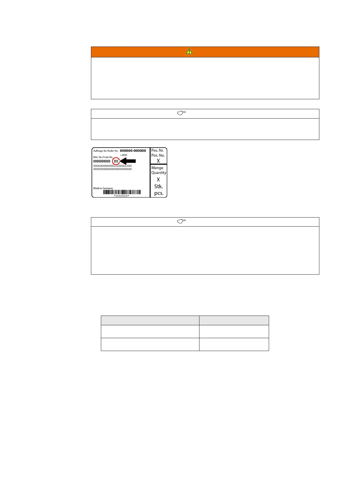
Fig. 106: Position of the component number (arrow)
Preconditions • The busbar cover is mounted.
• Identify the air guide components to be mounted in the corresponding panel using one of
the component tables. The component table to use depends on the degree of protection of
the panel.
WARNING
Pressure wave, intense heat or escaping gases
Can cause serious injury or property damage.
On panels with a panel width of 900 mm, air guides must be mounted. Without air guides, the
internal arc classification of the switchgear is not guaranteed.
➭ Mount the air guides.
INFORMATION
The components of the air guides are delivered with the switchgear accessories and are marked
with a component number. With the following component tables, the numbers of the
components required for the corresponding panel can be identified.
INFORMATION
Before mounting the air guides, the following information must be at hand for each panel:
• Is the panel equipped with voltage transformers at the busbar (yes or no)
• Height of low-voltage compartment (760 mm or 1160 mm)
• Degree of protection of the panel (IP3XD, IP31D, IP32D or IP34D, see single-line diagram)
• Type of installation of the switchgear (wall-standing arrangement or free-standing
arrangement)
Degree of protection Component table
IP3XD see page 152, "Component table
1"
IP31D, IP32D or IP34D see page 152, "Component table
1"
 Loading...