802-9081.9 • INSTALLATION AND OPERATING INSTRUCTIONS • NXPLUS C • Revision 11 203/293
Operation
23 Verification of safe isolation from supply
23.1 LRM plug-in sockets
➭ Remove the covers from the plug-in sockets (interfaces of phases L1, L2 and L3).
➭ Insert the LRM voltage indicator consecutively into the plug-in sockets of the phases L1, L2
and L3.
✔ If the LRM voltage indicator does not flash or light up in any of the 3 phases, the phases are
not live.
DANGER
Hazardous voltage
Will cause death, serious injury or considerable property damage.
Verify safe isolation from supply.
➭ Possible sources of failure:
- Defective voltage indicator (or device for function testing of the coupling section)
- Maloperation of the voltage indicator (or device for function testing of the coupling
section)
➭ Test the function of the voltage indicator and the coupling section in accordance with
national standards:
- On a live panel
- With a test unit according to IEC 61243-5/EN 61243-5
- On all phases
➭ Use only voltage indicators or devices according to EN 61243-5 / IEC 61243-5 / VDE 0682-
415 to test the function of the coupling section. The interface conditions have not changed
as against the old standard VDE 0681 Part 7; the corresponding indicators can still be used.
➭ Perform repeat test of interface conditions at the capacitive interfaces, as well as on the
indicators according to the customer's specifications or national standards.
➭ Do not use short-circuiting jumpers as separate plugs. The function of the surge arrester
installed is not provided if short-circuiting jumpers are used.
INFORMATION
The following descriptions do not substitute reading the manufacturer documentation.
➭ Before using the voltage detecting systems, read the supplied manufacturer
documentation.
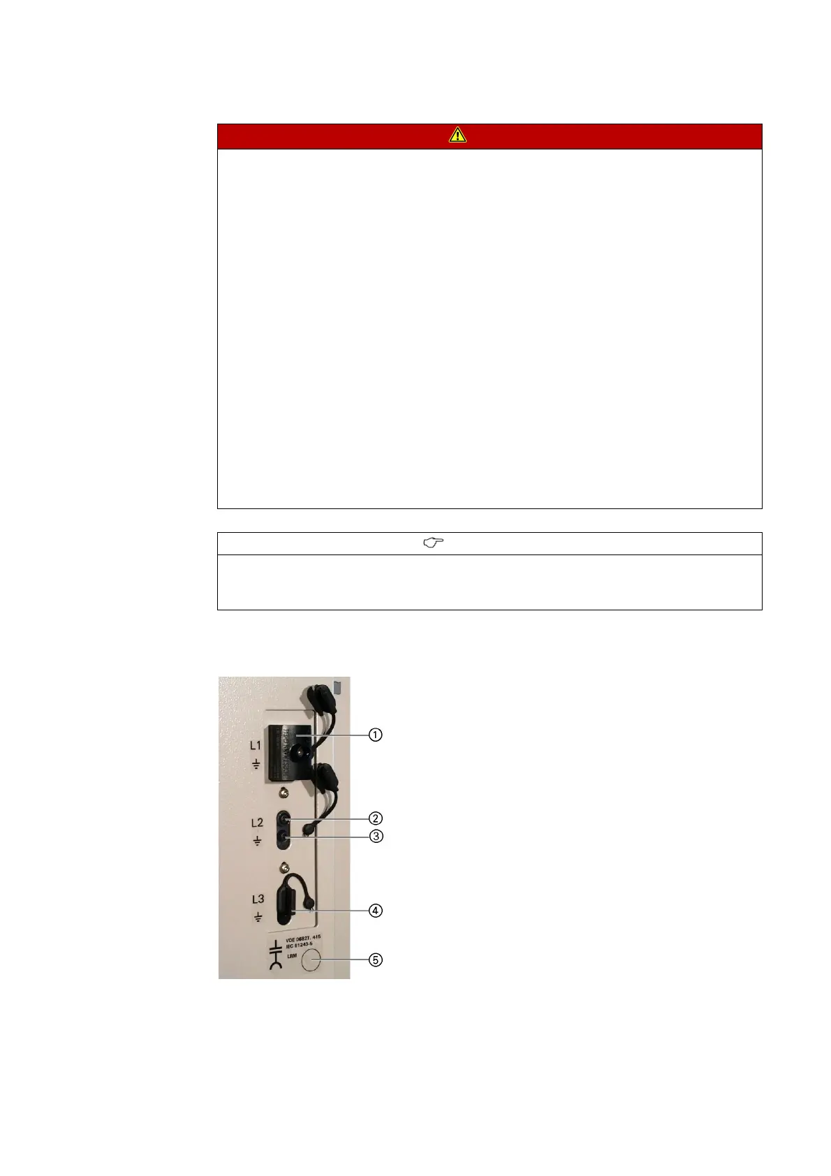
Fig. 167: LRM plug-in sockets
①
LRM voltage indicator
②
Plug-in socket (interface phase L2)
③
Earthing socket (interface phase L2)
④
Cover
⑤
Documentation to repeat test of interface
condition
 Loading...