802-9081.9 • INSTALLATION AND OPERATING INSTRUCTIONS • NXPLUS C • Revision 11 149/293
Installation
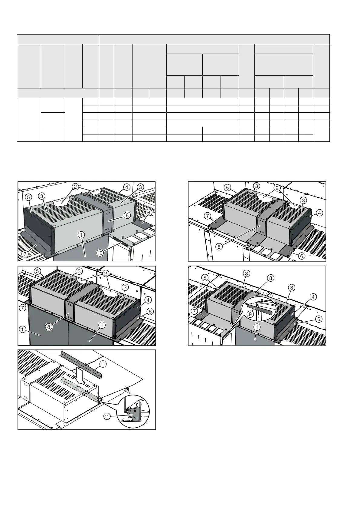
Component tables 3 and 4: Examples for busbar covers (view from the rear)
900
Intermedi
ate panel
760
No --- 102 05 111 106 97 98 99 100 126
Yes --- 102 05 111 106 97 98 99 100 126
Left end
panel
No --- 102 05 111 106 97 --- 99 --- 126
Yes --- 102 05 111 106 97 --- 99 --- 126
Right end
panel
No --- 103 05 --- 119 --- --- 98 --- 100
127
Yes --- 103 05 --- 119 --- --- 98 --- 100
1
Only for panels with feeder current ≤ 1000 A.
2
Mount only one left-hand or right-hand side wall each.
3
Only for left-hand or right-hand adjacent panel with a panel width of 600 mm.
Switchgear panel Components
Panel width
[mm]
Position
Height of
LV compartment
Pressure relief
Supporting angle
1
Cover
Side wall
2
Angle plate
Reinforcing plate
Sealing angle
3
Angle
Widht of left-
hand adjacent
panel [mm]
Width of right-
hand adjacent
panel [mm]
Type of installation of
the switchgear
600 900 600 900 Wall Free
Number in exemplary illustration: ① ③ ④ ⑤ ⑥ ⑥ ⑦ ⑦ ⑧ ⑨ ⑩ ⑨ ⑩ ⑪
 Loading...