Installation
162/293 Revision 11 • INSTALLATION AND OPERATING INSTRUCTIONS • NXPLUS C • 802-9081.9
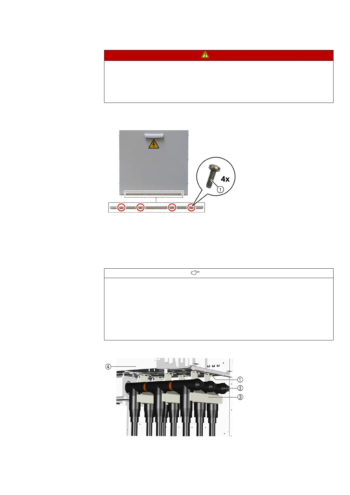
➭ Hook the cable compartment cover in. Refit the 4 bolts.
➭ Fasten the cable compartment cover at the lower edge using self-tapping bolts with cutting
ring size M5 (tightening torque: 7 Nm).
Connecting up to four
cables per phase
Up to 4 cables (plugs) can be connected per phase for 600-mm-wide panels.
After each three-phase cable connection, another arcing plate must be mounted in the cable
compartment. In like manner, the associated floor plate of the floor cover must be mounted
after each installed row of cable T-plugs (see page 156, "Mounting the floor plates").
Example: Installation of 3 cables per phase
DANGER
Internal arcing hazard and explosion hazard
Will cause death, injury or considerable property damage.
If the cable compartment cover is not bolted tight, the switchgear is not arc-resistant.
➭ Bolt the cable compartment cover together with the switchgear frame. Use the bolts with
cutting ring supplied with the switchgear.
Fig. 121: Earthing the cable compartment cover
①
Bolt with cutting ring
INFORMATION
The arcing plates in the cable compartment have been pre-assembled at the factory. For
cable installation, the arcing plates must be removed.
➭ After cable installation, position the arcing plates as close as possible to the front towards
the cables according to the cable T-plugs used.
➭ The distance between the arcing plates and the cable T-plugs must not exceed a maximum
of 15 mm.
➭ The mounted arcing plates must not touch the cable T-plugs.
➭ Do not damage the cable T-plugs while mounting the arcing plates.
Fig. 122: Arcing plates at the cable connection: Three cables per
phase
①
Fastening at the partition to
the operating mechanism
compartment
②
Cable T-plugs
③
Air guide
④
Switchgear vessel
 Loading...