51 / 62
Siemens RDF302 Basic documentation CE1P3079en
Smart Infrastructure 2022-06-17
4. Handling
4.1 Mounting and installation
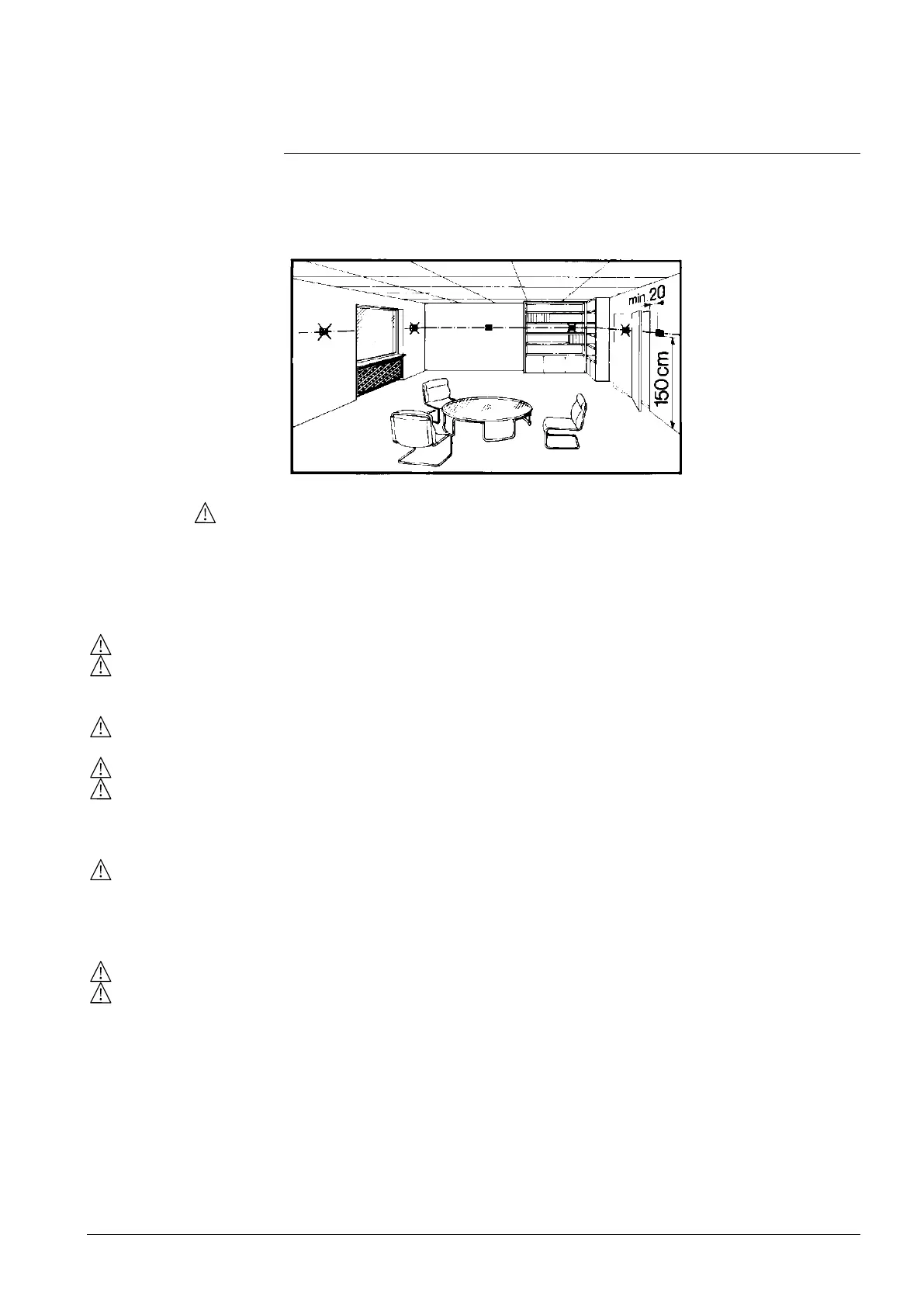
Mount the room thermostat on a recessed square conduit box with 60.3 mm fixing
centers. Do not mount on a wall in niches or bookshelves, behind curtains, above
or near heat sources, or exposed to direct solar radiation. Mount about
1.5 m above the floor.
• Mount the room thermostat in a clean, dry indoor place without direct airflow
from a heating / cooling device, and not exposed to dripping or splash water
• In case of limited space in the conduit box, use mounting bracket ARG70.3 to
increase the headroom by 10 mm
See Mounting Instructions M3079 enclosed with the thermostat.
• Comply with local regulations to wire, protection and earth the thermostat.
• The device has no internal fuse for supply lines to fan and actuators. To avoid
risk of fire and injury due to short-circuits, the AC 230 V mains supply line must
have a circuit breaker with a rated current of no more than 10 A.
• Properly size the cables to the thermostat, fan and valve actuators for
AC 230 V mains voltage.
• Use only valve actuators rated for AC 230 V
• The wiring cross section used for power supply (L, N), fan/relays (Qxx) and
230 V outputs (Yxx -N) must be adapted to the preceding overload protection
elements (max 10A) under all circumstances. Comply under all circumstances
with local regulations.
• Cables of SELV inputs X1-M / X2-M: Use cables with min AC 230 V insulation,
as the conduit box carries AC 230 V mains voltage.
• Inputs X1-M or X2-M: Several switches (e.g. summer / winter switch) may be
connected in parallel. Consider overall maximum contact sensing current for
switch rating.
• Isolate the cables of Modbus communication input +, - and REF for 230 V.
• No metal conduits.
• No cables provided with a metal shield.
• Disconnect from supply before opening the cover.

 Loading...