Introduction
1.3Required Tools and Materials
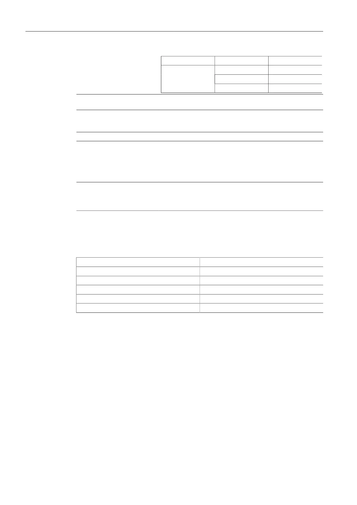
Mode Color/State Description
Green (Blinking) 1000 Mbps
Orange (Solid) 10 Mbps
Off No link detected
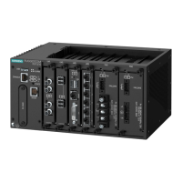
Display Mode Indicator LEDs The display mode indicator LEDs indicate the current display mode
for the port status indicator LEDs (i.e. Status, Duplex or Speed).
Mode Button The Mode button sets the display mode for the port status indicator
LEDs (i.e. Status, Duplex or Speed). It can also be used to reset the
device if held for 5 seconds.
Alarm Indicator LED The alarm indicator LED illuminates when an alarm condition exists.
Power Module Indicator LEDs The power module indicator LEDs indicate the status of the power
modules.
• Green – The power supply is supplying power
• Red – Power supply failure
• Off – No power supply is installed
RS-232 Console Port The serial console port is for interfacing directly with the device and
accessing initial management functions. For information about con-
necting to the device via the serial console port, refer to "Connect-
ing to the Device (Page 21)".
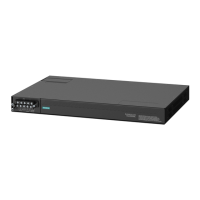
1.3 Required Tools and Materials
The following tools and materials are required to install the RUGGEDCOM RSG2100:
Tools/Materials Purpose
AC power cord (16 AWG) For connecting power to the device.
CAT-5 Ethernet cables For connecting the device to the network.
Flathead screwdriver For mounting the device to a DIN rail.
Phillips screwdriver For mounting the device to a panel.
4 x #8-32 screws For mounting the device to a panel.
1.4 Decommissioning and Disposal
Proper decommissioning and disposal of this device is important to prevent malicious
users from obtaining proprietary information and to protect the environment.
Decommissioning
This device may include sensitive, proprietary data. Before taking the device out of
service, either permanently or for maintenance by a third-party, make sure it has
been fully decommissioned.
For more information, refer to the associated Configuration Manual.
RUGGEDCOM RSG2100
Installation Manual, 03/2020, C79000-G8976-1040-17
3
 Loading...