Installing the Device
2.4.2Mounting the Device on a DIN Rail
• Do not overload the supply circuit. Refer to the over-current protection and pow-
er supply ratings specified by the rack manufacturer.
• Make sure the rack and all devices have a proper ground-to-Earth connection.
Pay particular attention to power supply connections other than direct connec-
tions to the branch circuit (e.g. power strips).
To secure the device to a standard 48 cm (19 in) rack, do the following:
Note
The device can be ordered with the communication ports located at the front or rear
of the device. Placing the ports at the rear allows all data and power cabling to be in-
stalled and connected at the rear of the rack.
1. Make sure the rack mount adapters are installed on the correct side of the chas-
sis.
• To make the modules and ports accessible, install the rack mount adapters
at the rear of the chassis
• To make the management ports and LEDs accessible, install the rack mount
adapters at the front of the chassis
Note
The chassis features multiple mounting holes, allowing the rack mount adapters
to be installed up to 25 mm (1 in) from the face of the device.
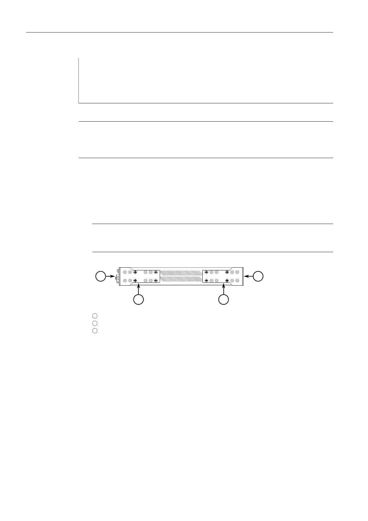
1
Rear
2
Front
3
Rack Mount Adapter
Figure2.2 Rack Mount Adapters
2. If required, install adapters on the opposite side of the device to protect from vi-
brations.
3. Insert the device into the rack.
4. Secure the adapters to the rack using the supplied hardware.
2.4.2 Mounting the Device on a DIN Rail
For DIN rail installations, the RUGGEDCOM RSG2100 can be equipped with panel/DIN
rail adapters pre-installed on each side of the chassis. The adapters allow the device
to be slid onto a standard 35 mm (1.4 in) DIN rail.
RUGGEDCOM RSG2100
Installation Manual, 03/2020, C79000-G8976-1040-17
11
 Loading...