Installation Instructions
13
scheme .
Before attempting to install the trip unit, check the label on the
side of the unit to make sure that it is the proper unit for the
SB breaker. A built-in rejection scheme will prevent the
installation of a trip unit into a breaker for which it is not
intended.
Electronic Trip Unit
4.) Check label on side of trip unit
This scheme consists of two pins on the support plate on
which the trip unit will set into two matching holes in the
bottom of the trip unit. If the holes in the bottom of the trip unit
cannot be aligned with the pins, the trip unit cannot be
installed in the SB breaker. If there is any doubt about a trip
unit being the proper trip unit for a breaker, hold the trip unit
upside down and check the alignment of the pins and holes
5.) Check for proper pin alignment
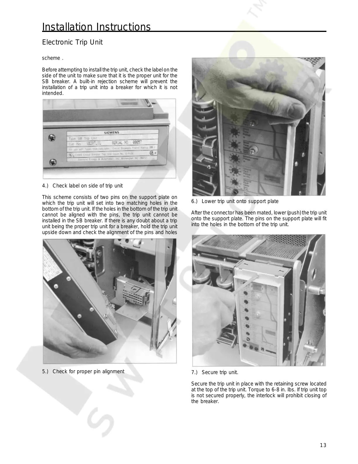
6.) Lower trip unit onto support plate
After the connector has been mated, lower (push) the trip unit
onto the support plate. The pins on the support plate will fit
into the holes in the bottom of the trip unit.
7.) Secure trip unit.
Secure the trip unit in place with the retaining screw located
at the top of the trip unit. Torque to 6-8 in. Ibs. If trip unit top
is not secured properly, the interlock will prohibit closing of
the breaker.
Courtesy of NationalSwitchgear.com
 Loading...