56
Internal Accessories
Shunt Trip
CAUTION: Do not attempt to install an accessory with
the breaker “Closed” or “Charged”. Make certain breaker
is “Open” and “Discharged” as shown above. Personal
injury or mechanical damage may occur. Preliminary
installation procedures are outlined on pages 36-37.
Shunt Trip Kit
Shunt Trip
The shunt trip provides the capability to open the SB breaker
from a remote location . Shunt trips are available to operate
with a source power of 120, 240, or 480V ac, 12, 24, 48, or
125V dc. The shunt trip accessory kit consists of a trip
solenoid to open the breaker, a clearing switch to remove
voltage from the solenoid coil upon the breakers opening and
mounting hardware.
To install the shunt trip, first remove the breaker front cover
and trip unit, if previously installed (see page 37). Pinching
wires is not a problem when removing the cover.
1.) Remove the rubber band from the shunt trip assembly.
Be careful not to drop and damage the plunger.
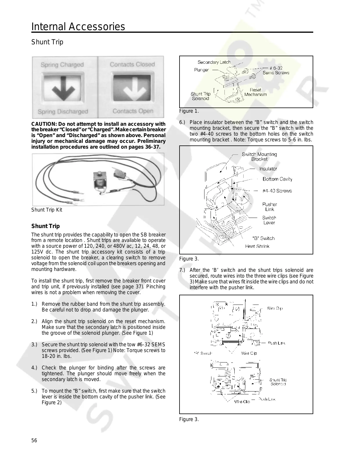
2.) Align the shunt trip solenoid on the reset mechanism.
Make sure that the secondary latch is positioned inside
the groove of the solenoid plunger. (See Figure 1)
3.) Secure the shunt trip solenoid with the tow #6-32 SEMS
screws provided. (See Figure 1) Note: Torque screws to
18-20 in. Ibs.
4.) Check the plunger for binding after the screws are
tightened. The plunger should move freely when the
secondary latch is moved.
5.) To mount the “B” switch, first make sure that the switch
lever is inside the bottom cavity of the pusher link. (See
Figure 2)
Figure 1.
6.) Place insulator between the “B” switch and the switch
mounting bracket, then secure the “B” switch with the
two #4-40 screws to the bottom holes on the switch
mounting bracket . Note: Torque screws to 5-6 in. Ibs.
Figure 3.
7.) After the ‘B’ switch and the shunt trips solenoid are
secured, route wires into the three wire clips (see Figure
3) Make sure that wires fit inside the wire clips and do not
interfere with the pusher link.
Figure 3.
Courtesy of NationalSwitchgear.com
 Loading...