Wiring
3.2 Pin assignment
I/O device digital inputs DI 16x24VDC M12-L 8xM12 (6ES7141-6BH00-0BB0)
14 Equipment Manual, 06/2021, A5E46570510-AB
Bus interface with integrated 2-port switch
Supply voltage 1L+ (non-switched)
Load voltage 2L+ (switched)
④ 2-wire connection (dual assignment of the
2M Ground 2M (switched)
⑤ 3-wire connection (dual assignment of the
1US 24 V encoder supply (from 1L+)
RUN/network status LED (green)
ERROR/module status LED (red)
Infeed of supply and load voltage
MAINT/IO status LED (yellow)
Loop-through of supply and load voltage
PROFINET interface X1 port 1
PROFINET interface X1 port 2
Channel status/channel error LED (green/red)
Figure 3-1 Terminal and block diagram
3.2 Pin assignment
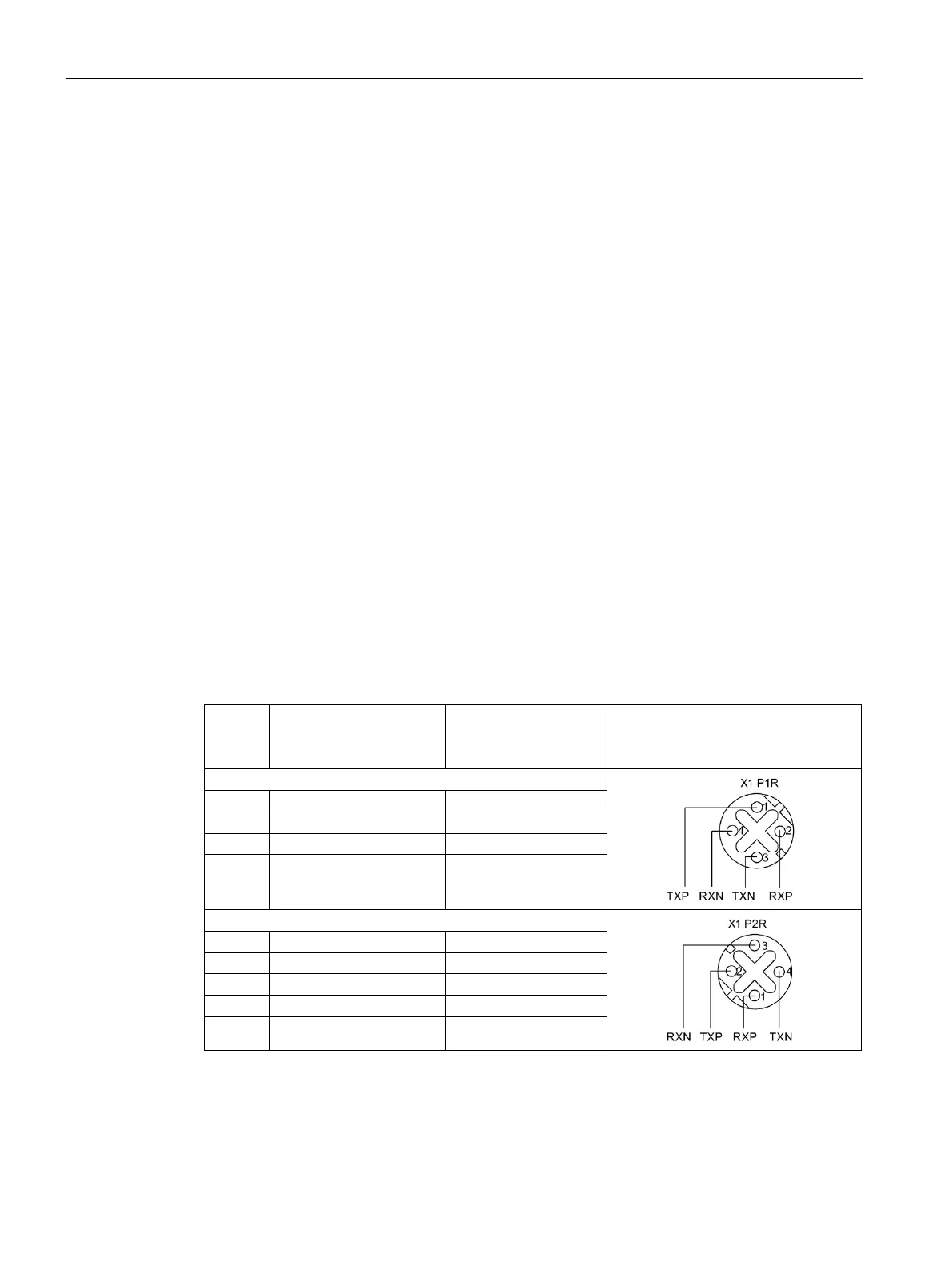
Terminal assignment PROFINET connector
The following table shows the pin assignment of the PROFINET connector.
Table 3- 1 Pin assignment of the PROFINET connector, port 1 and 2
Pin Assignment of the core
color of the PROFINET
Assignment Front view of the connectors

 Loading...