Getriebe − Nocken − Endschalter Reihe 51 / 51 DZ
Geared Cam Limit Switches Series 51 / 51 DZ
21
Datum / Date 10.2008
Beim Einsatz einer zusätzlichen Nockenscheibengruppe
(verlängert den Schalter um 10,5 mm) kann die Einstel−
lung des Potentiometers mit der letzten Verstellschnecke
ohne das Lösen von Schrauben und Muttern erfolgen. Die
Poti − Einstellung mit zusätzlicher Nockenscheibengruppe
kann nur in Ausführung "N" erfolgen.
b) Potikupplung "S"
Die Kupplung dreht synchron mit der Eingangsdrehzahl
der Nockenscheibengruppe. Der nutzbare Drehwinkel für
die Potentiometer ist max. 1470_ (345_x4,285). Für diese
Drehwinkel werden üblicherweise Mehrfach − Wendel −
Potentiometer eingesetzt.
Zusätzlich eingebaute Potentiometer vergrößern unter Um−
ständen die Baulänge der Getriebe − Schalter. Für die Angabe
der genauen Baulänge bitten wir um Rückfrage, evtl. unter
Angabe der Potentiometermaße.
When fitting an additional cam disc assy (extends the
switch by 10.5 mm), the potentiometer can be adjusted
by the last adjusting worm without having to lose the
screws and nuts. The potentiometer adjustment with addi−
tional cam disc assy is possible with execution "N" only.
b) Potentiometer coupling "S"
This coupling turns synchronous with the input speed of
the cam disc group. The usable angle of rotation for the
potentiometer is maximum 1470_ (345_x4.285). For this
angle of rotation, multi − turn potentiometers are normally
used.
Additionally installed potentiometers may increase the overall
length of the geared switch.
For the exact overall length please consult us stating the po−
tentiometer dimensions.
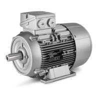
Beispiel für Potianbau/Example of potentiometer mounting
Potentiometer
DD1_40288V
(SW 15)
~16
Gummieinsatz
ø 23
Aufnahmebohrung für Potiwelle
Klemm − Mutter PG 7
ø 6
~19
DD1_40290V
Clamping nut
Rubber insert
Locating hole for potentiometer shaft
Mdmax. = 10 Ncm
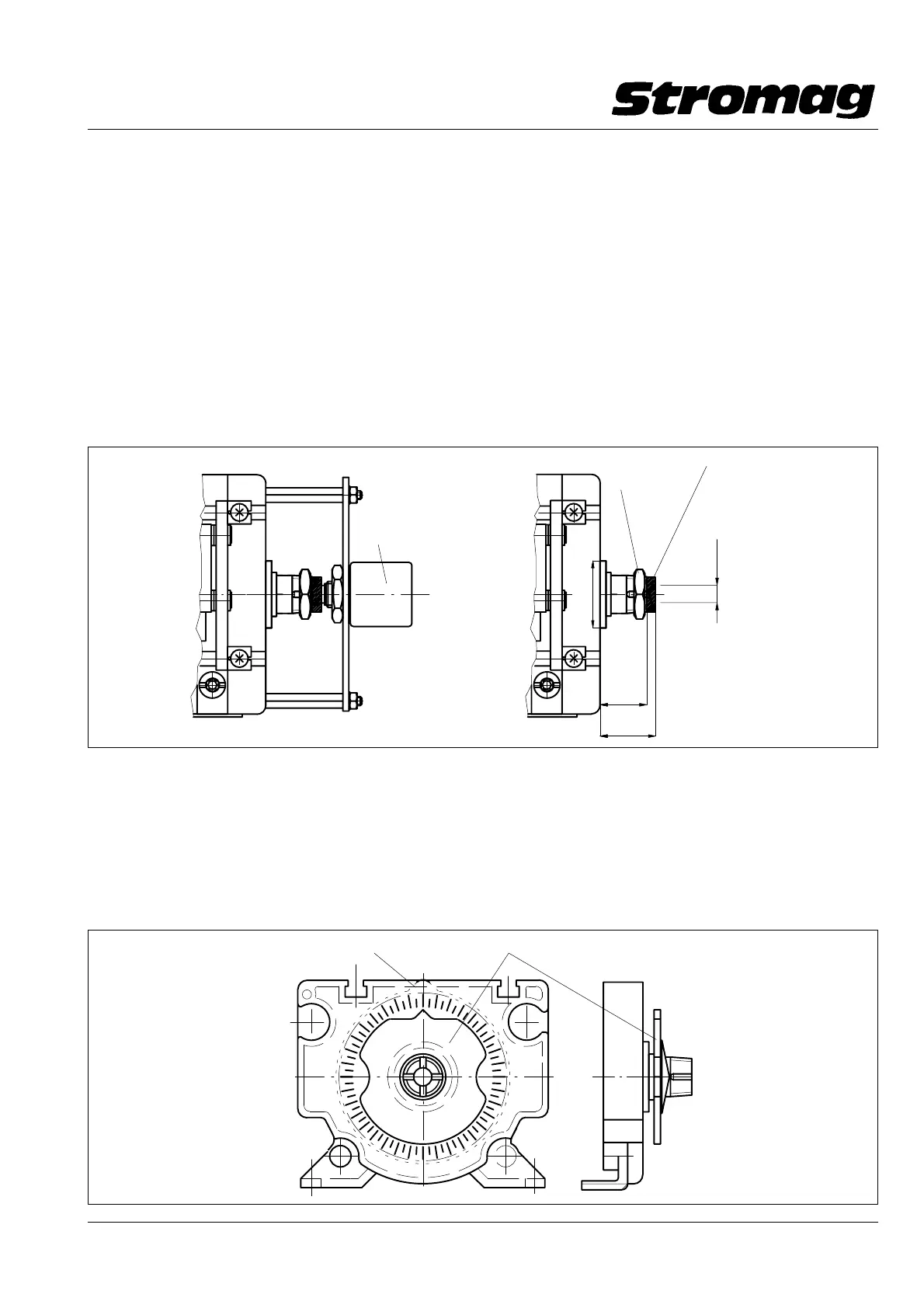
2.3 Anzeigescheibe (nur bei Reihe 51 möglich)
Die Anzeigescheibe zur Blockverstellung (auf Wunsch gegen
Mehrpreis lieferbar) dient dazu, die Verstellung der Schalter
mittels Blockverstellung zu erleichtern. Die durch Reibschluß
gehaltene Anzeigescheibe wird auf eine Referenzmarke ein−
gestellt und erleichtert dadurch den späteren Abgleich auf
diese Referenzmarke mittels der Blockverstellschnecke we−
sentlich. Unter Umständen wird durch die Anzeigescheibe ein
zusätzliches Gehäuse − Zwischenstück nötig.
2.3 Indicating plate (only possible for series 51)
The indicating plate for block adjustment (available at an ad−
ditional charge on request) serves to facilitate adjustment of
the switch by means of block adjustment. The friction locked
indicating plate is set at a reference mark which thus conside−
rably facilitates subsequent adjustment to this reference mark
by means of the block adjusting worm. The use of the indica−
ting plate may make an additional housing intermediate piece
necessary.
Nockenscheibe / Cam disc
Anzeigescheibe / Indicating plate
DD1_40291V
 Loading...