Getriebe − Nocken − Endschalter Reihe 51 / 51 DZ
Geared Cam Limit Switches Series 51 / 51 DZ
23
Datum / Date 10.2008
2.5 Impulsgeber I 49
Speziell für den Einsatz in Mobilkranen wurde ein Impulsge−
ber mit besonderen technischen Eigenschaften entwickelt. Es
wird magnetisch ein Zahnrad mit 50 Zähnen abgetastet (50
Impulse/Umdrehung). Die Elektronik ist für den Betrieb in ei−
nem Fahrzeug − Bordnetz vorgesehen und ist besonders ge−
schützt gegen die in diesen Netzen auftretenden Überspan−
nungen. Der Versorgungsspannungs − Anschluß ist ver −
polungssicher. Der einkanalige Impulsgeberausgang kann in−
duktive Lasten bis zu einem Strom von ca. mittl. 110 mA trei−
ben und er ist kurzschlußfest. Um eine zu starke Erwärmung
der anzuschließenden Hubmagnetspulen bei einem Dauersi−
gnal zu verhindern, schaltet der Ausgangsverstärker jeden
Impuls nach ca. 20 ms aus (Monoflop − Funktion).
Mit diesem Impulsgeber wird eine Drehung des Endschalters
angezeigt und es kann die Geschwindigkeit erkannt werden.
Eine Erkennung der Rechts − und Linksdrehrichtung ist nicht
möglich.
2.5 Pulse transmitter I 49
This pulse transmitter has been specially developed for use
in mobile cranes and has special technical features. A toothed
wheel with 50 teeth is magnetically scanned (50 pulse/revolu−
tion). The electronic circuitry is designed for operation in a
motor vehicle supply system and is specially protected
against the overvoltages occurring on these systems. The
supply voltage connection is protected against polarity rever−
sal. The single channel pulse transmitter output can drive in−
ductive loads up to a current of on average approx. 110 mA
and is short − circuit proof. To prevent excessive heating of the
solenoid coils to be connected, with a continuous signal, the
output amplifier disconnects each pulse after about 20 ms
(monoflop function).
With this pulse transmitter, rotation of the limit switch is indica−
ted and the speed can be identified. It is not possible to di−
stinguish between clockwise and counter − clockwise rotation.
DD1 40565H
Technische Daten / Technical data
Betriebsspannung/Service voltage 24V DC (18 − 36V DC)
Stromaufnahme/P ower consumption ca./approx. 180 mA
Ausgang/Output mittl./on average 110 mA
Impulsdauer/Pulse duration ca./approx. 20 ms (Monoflopfunktion/monoflop function)
Temperaturbereich/T emperature range − 40°C bis/to +85°C
− Kurzschlußfester Ausgang / Output short circuit proof
− Versorgungsspannung verpolungssicher / Supply voltage protected against exchange of poles
− Funtionskontrolle mittel gelber Leuchte / Performance check by yellow LED
− 50 Impulse/Umdrehung; Pulses/rev.
− keine Abgleich − und Einstellarbeiten / no aligning and adjusting works
− Anschluß über Flachstecker / Connection through flat plug 6.3 mm x 0.8
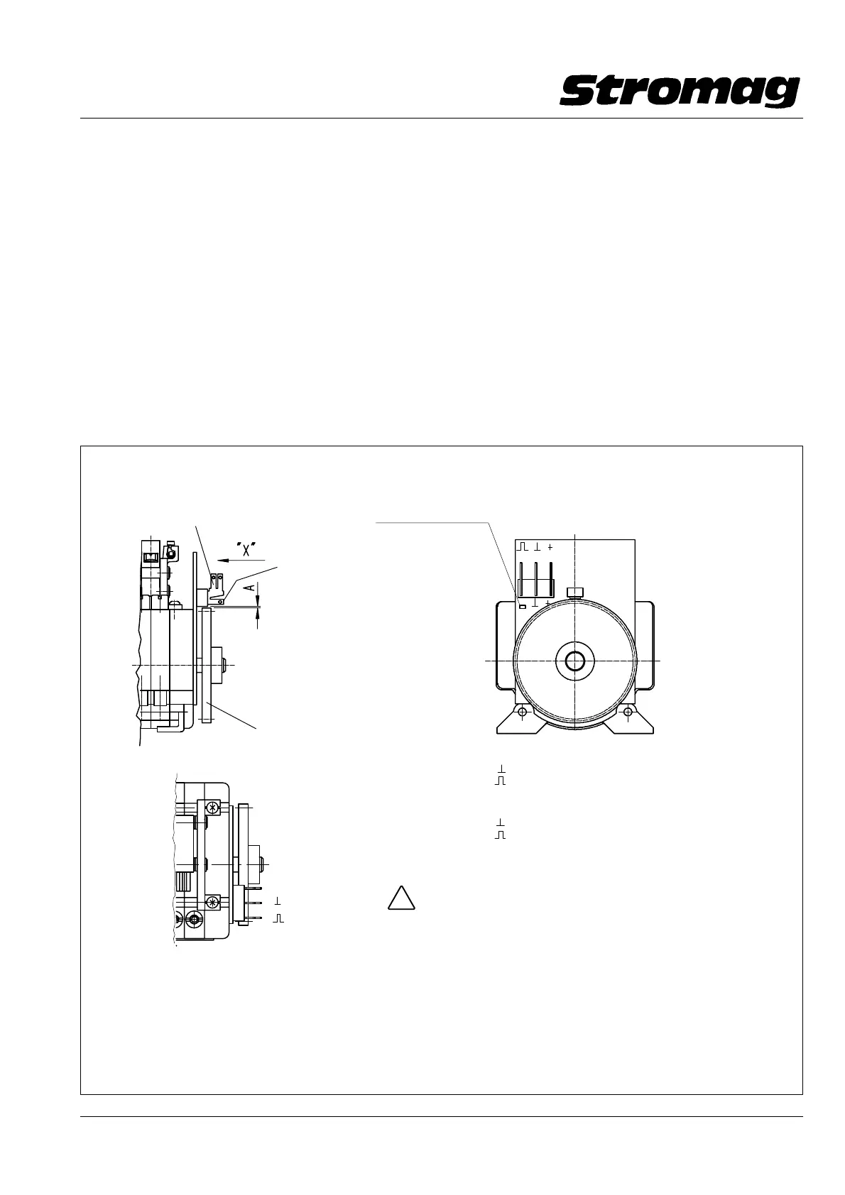
Output
Ground
+ 24V =
Ansicht / View "X"
Connections:
+24v= − supply voltage +18V to +36V d.c
Ground − GND
Output − output signal
LED as performance check
LED als Funktionskontrolle
+24V= − Versorgungsspg. +18V − +36V DC
Ground − Masse
Output − Ausgangimpuls
Anschlüsse:
Achtung / Caution
Falscher Anschluß kann zu Zerstörung führen!
wrong connection can cause destruction!
Impulsgeber mit 50 Impulsen/Umdrehung für Endschalter der Reihe 51 zur Montage an der B − Seite des Schalters
Pulse generator with 50 pulses/rev. fitted to the B − side of the limit switch
Flachstecker/Flat plug 6.3 mm x 0.8
Flachstecker/Flat plug 2.8 mm x 0.8
Meßabstand/Measuring distance A X 0.2 mm
Zahnrad mit 50 Zähnen
Toothed wheel with 50 teeth
!
 Loading...