Installation 10.98
6SE7087-6KP50 Siemens AG
5-6 Operating Instructions SIMOVERT MASTERDRIVES
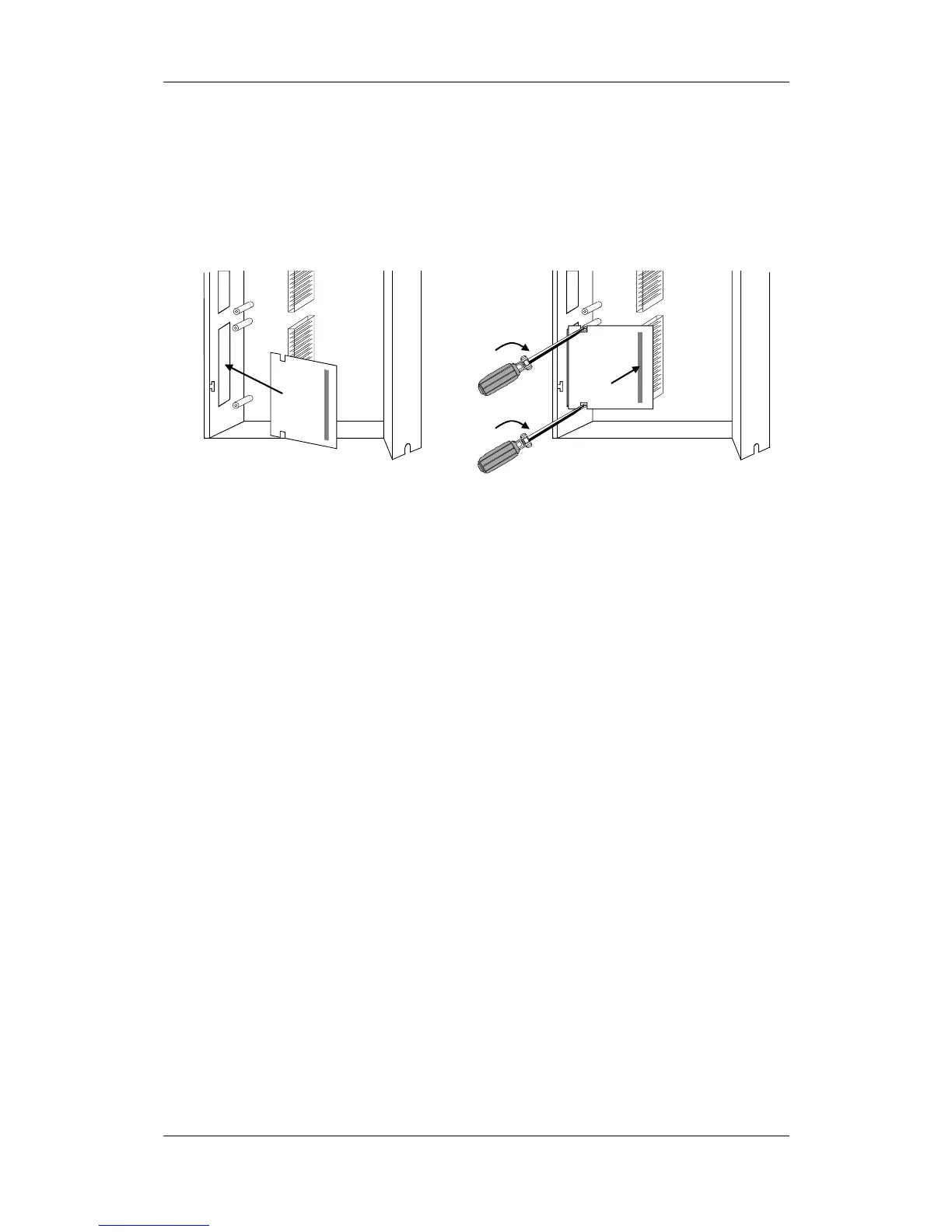
Push the optional board from behind into the opening on the front cover
(
) until the position of the 64-pole system connector on the main
board corresponds with the position of the socket.
Insert the optional board from the right onto the 64-pole system
connector on the main board (
ó). The view shows the installed state.
Screw the optional board tight at the fastening points in the front section
of the optional board (
ì).
Slot B
Slot C
Rear wall
ó
ì
Slot C
Rear wall
ì
Fig. 5-6 Installing the optional board
Close the right-hand side wall of the unit as follows
♦
Insert the right-hand side wall from above into the guide on the front
right-hand side.
♦
Swing back the side wall.
♦
Screw the side wall tight again by means of the two fixing screws.
Mount the unit as follows:
♦
Insert the unit into its mounting position from the front underneath
the DC link bus module.
♦
Lift the unit upwards until the DC link bus module is completely in its
original position again.
♦
Screw the unit tight to the mounting surface with the fixing screws.
♦
Interlock the DC bus module.
♦
Re-connect all previously removed connecting cables.
♦
Check all connecting cables and the shield to make sure they sit
properly and are in the correct position.
♦
To designate the optional board, insert the relevant designation
plate into the envisaged position on the front of the unit.
♦
After powering up the voltage, you can log on the optional boards in
the software of the unit and commence start-up.
Installing the
optional board
Assembling and
mounting the unit
Designating the
optional board
 Loading...


