10.98 Description
Siemens AG 6SE7087-6KP50
SIMOVERT MASTERDRIVES Operating Instructions 2-1
2 Description
The inverter is a power electronics component for feeding highly
dynamic three-phase drives in the output range from 0.75 kW to
18.5 kW.
The unit can be operated from a DC system with voltages from 510 V to
650 V.
The inverter enables a three-phase system with a variable output
frequency between 0 Hz and 400 Hz to be generated from the DC link
voltage with the pulse width modulation method (PWM).
The unit is controlled by the internal closed-loop control electronics
which consists of a microprocessor and a digital signal processor
(DSP). The functions are provided by the unit software.
The unit can be operated via the PMU operator control panel, the user-
friendly OP1S operator control panel, the terminal strip or via the bus
system. For this purpose, the unit has a number of interfaces and three
slots for the use of optional boards.
Resolvers, encoders, pulse encoders and multiturn encoders can be
used as encoders on the motor.
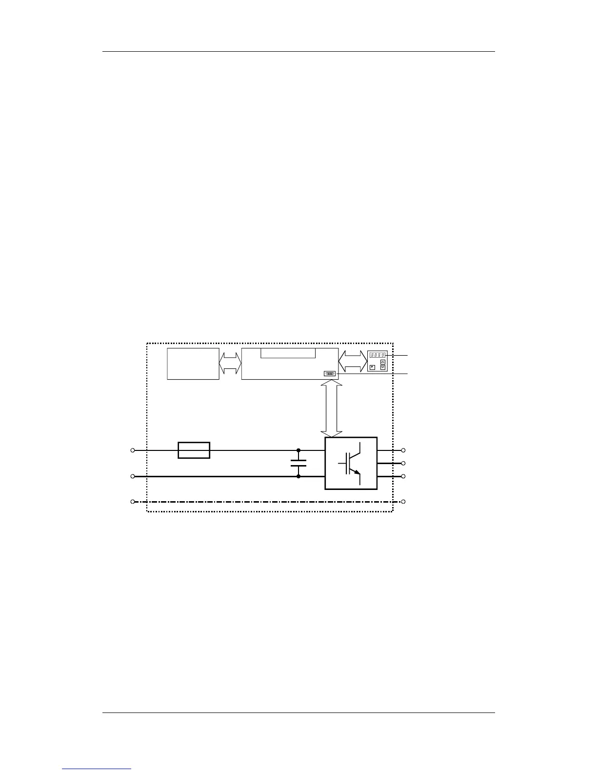
Motor
terminals
U2/T1
V2/T2
W2/T3
PE2
Control electronics
Serial
interf ace
Terminal strip
Optional
boards
DC
link
C / L+
D / L -
PE3
PMU
Inverter
DC link
fuse
Fig. 2-1 Circuit principle of the inverter
Range of application
 Loading...


