Connecting-up 10.99
6SE7087-6KP50 Siemens AG
7-4 Operating Instructions SIMOVERT MASTERDRIVES
SIEMENS
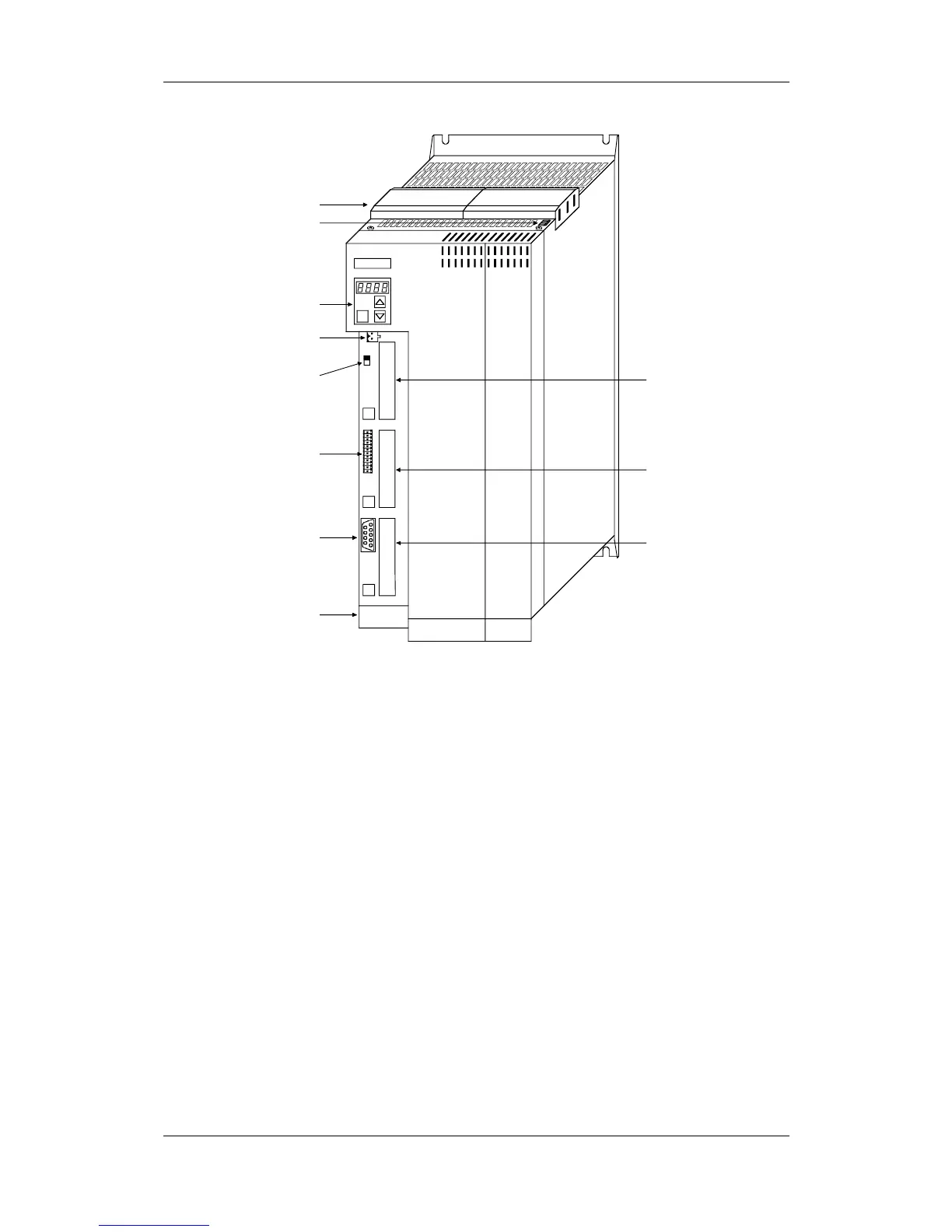
A
S1
BX101
CX103
P
PMU
DC24 V supply,
RS485 (USS) X100
Bus terminating
resistor (USS) S1
Terminal strip X101
RS232/RS485 (USS) X103
Motor connection X2
PE3
−
+
Slot A
Slot B
Slot C
DC link bus module X3
Safe OFF (option) X533
Fig. 7-3 Connection overview of units 180 mm wide
7.1 Power connections
The protective conductor must be connected up both on the mains side
and on the motor side.
On account of leakage currents through the interference-suppression
capacitors, a minimum cross-section of 10 mm² must be used in
accordance with VDE 0160. If mains connections with cross-sections
less than 10 mm² are used, the following measures can be applied.
If the unit is mounted on a grounded mounting surface via a conductive
connection, the protective conductor cross-section can be the same as
that of the supply-cable conductor.
In the case of insulated installation or a poor conductive connection to
the mounting surface, a separate protective conductor with a cross-
section of 10 mm² can be connected up instead of the protective
conductor of the mains connection.
Protective
conductor
 Loading...


