Connecting-up 10.99
6SE7087-6KP50 Siemens AG
7-6 Operating Instructions SIMOVERT MASTERDRIVES
7.1.2 Power connections for units with a width of 135 mm and 180 mm
The DC link bus module serves to supply the unit with electrical energy.
Bar Designation Meaning Range
3 PE3 Protective conductor connection
2 D / L- DC link voltge - DC 510 - 650 V
1 C / L+ DC link voltage + DC 510 - 650 V
Connectable cross-section: "Electro-plated copper" 3x10 mm, rounded
off according to DIN 46433
Bar 1 is at the front when installed.
Table 7-3 DC link busbars
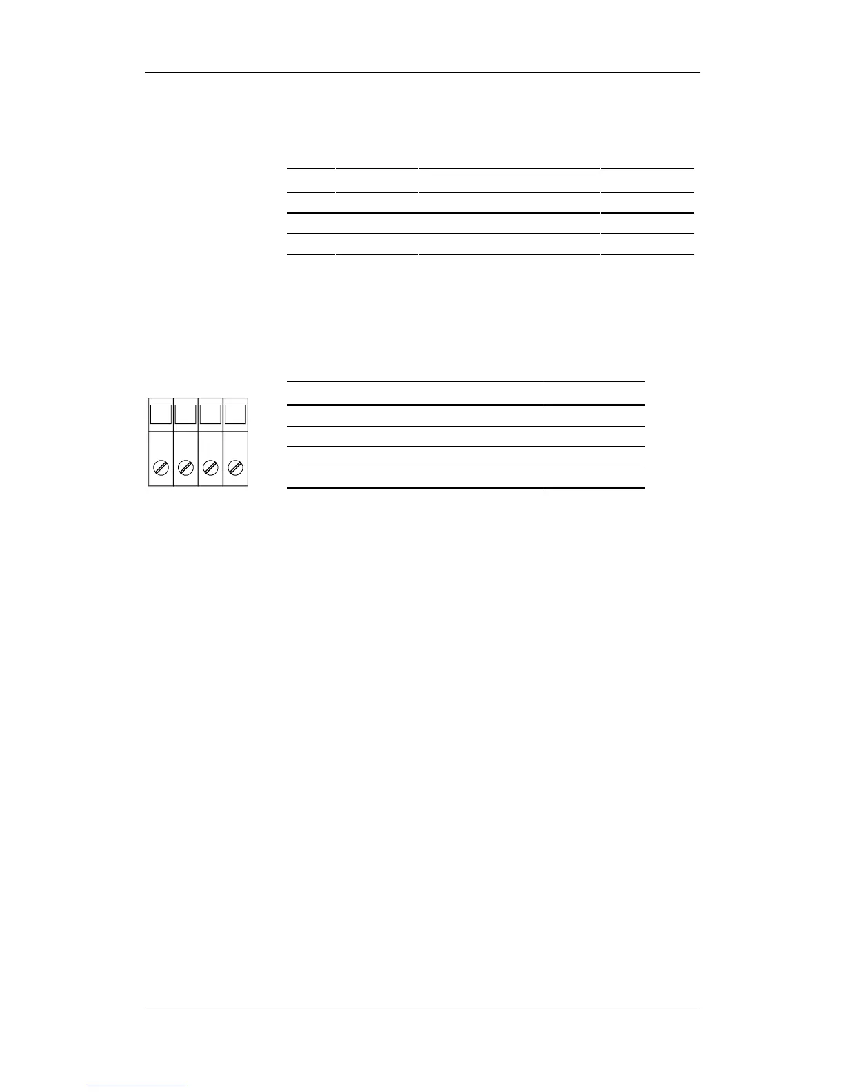
The motor connection is to a terminal block at the bottom of the unit.
Terminal Meaning Range
PE Protective conductor connection 3AC 380 - 480 V
U2 / T1 Phase U2 / T1 3AC 380 - 480 V
V2 / T2 Phase V2 / T2 3AC 380 - 480 V
W2 / T3 Phase W2 / T3 3AC 380 - 480 V
Connectable cross-section:
Housing width 135 mm: 10 mm² (AWG 8), stranded
Housing width 180 mm: 16 mm² (AWG 6), stranded
Viewed from the front, Terminal PE is at the left.
Table 7-4 Motor connection
X3 - DC link bus
module
X2 – Motor
connection
PE U2 V2 W2
 Loading...


