Forming 10.98
6SE7087-6KP50 Siemens AG
10-2 Operating Instructions SIMOVERT MASTERDRIVES
♦
Rectifier (A): SKD 62/16
♦
Resistor (R): 470
Ω
, 100 W
♦
Capacitor (C): 22 nF, 1600 V
The unit has hazardous voltage levels up to 5 minutes after it has been
powered down due to the DC link capacitors. The unit or the DC link
terminals must not be worked on until at least after this delay time.
♦
Before forming the DC link capacitors, you must remove the unit or
or remove the front and middle DC link busbars (C/L+ and D/L-).
♦
After you have removed the unit, connect PE2 to ground. Built-in
units are to be grounded to busbar PE3.
♦
Connect up the forming equipment as shown in the circuit diagram.
♦
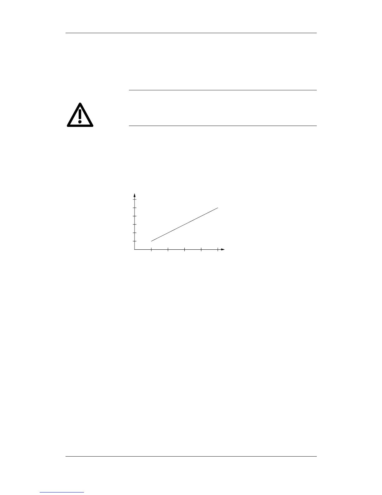
Switch on the forming circuit. The forming duration depends on the
length of time that the inverter has been out of action.
Off-circuit idle
time in years
Forming time
in hours
12345
1
2
3
4
5
6
Fig. 10-2 Forming time as a function of converter idle time
Components for the
forming circuit
(suggestion)
WARNING
Procedure
 Loading...


