4 Operating the Application
4.3 Monitoring and parameter access via operator panel
SINAMICS G120 DP at S7-1200
Entry-ID: 70155469, V1.4, 07/2018
Copyright Siemens AG 2018 All rights reserved
4.3.2 Process data exchange
Both screens for the process data exchange access the instance
idb_Process_Data data block (DB11).
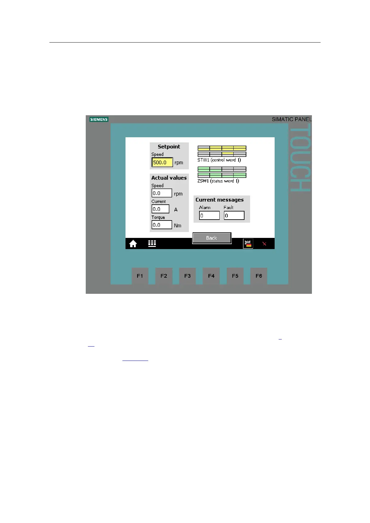
Control and status word
Figure 4-2: Control and status word
The displayed control or status word is identical with that in the Process_Data tag
table (see chapter 4.4).
STW1 (control word 1)
The buttons in the upper part of the screen are inactive (see footnote 5 on page
20). However, the color change indicates the logic states of the individual control
bits. Signal state “1” is indicated with yellow color. For running the motor, the bits
displayed in Figure 4-2 must be connected with signal state “1” and were therefore
given the default value “1” in the program.
ZSW1 (status word 1)
The text fields in the bottom screen section show the state of the individual bits of
the status word. Signal state “1” is indicated with green color. In contrast, “Fault
active” and “Alarm active” take on red or pink for state “1”.
 Loading...


